13. VOLUME PRE OUT 2
The VOLUI\'II Pre
Out 2 control allows for adjustment ofthe output
le\'el of the I'RE OIJT 2 sockets. The
outpul
lcvcl
can be rcduced
b,v
np
to l2dB; when set to the lllruiimnn
position
(at
the odB
positior),
the output level will he idcntictl
to that 0f the PRI OUT
I
sockets. Refer also to chapter
"Bi
amping" 1bI mole
in[orn]rtion.
,NOIE; alrva,vs turn thc
pfc-aorplifier
ancl associated
power
amplifiers off befo|e connecting or disconnecting an{hing
t0 thc
Pre-Out 1&2 sockels.
14, NAD LINK IN, OUT
Thc
\',\D-Link connector is useci to
pass
commands from
othcr
uniß litted t\'ith NAI)-l,ink
conncctors. Tlis alloqs centralised
control of a complete system, and also allows some
of the basic
furclions of
01her
NAD
componcnts
(such
as a CD
pla,ver
or
cxssette-deck) also equipped wilh l{,{D-Link to be c0ntrollcd with
the
pre-arnplificr's
rcmotc
coDtfol. To function
$jth
such otller
units, conrcct thc Cl60 s \AD Link Out to üe NADI-ink In
on thc
othef unil. NADl,ink
connccton can bc dxisv chxined, IN to OUI
so that a whole svsten can be controlled fronr üc renlote
control
facililics o[ onc uni1.
.I5.
12V TRIGGER
OUT
Thc l2V
Idgger is activlted aulomatica.lly \!hen s$itching thc
NAI)
C160 from off
or stand-bv
t0
on. Coonect the l2V trigger to r
po$ct
anrplitier or AC outlet
power
strip equippcd \rith
a 12V
lrigger inpul for fcnlotc on,/off
s\\itching of those devices. use a
cable teflninrted $ith a
3.5mn
Mini'Jack c0nnector
at the
pre
mrylifier"s
cnd
firr
conncction.
16. AC LINE
CORD
Plug
the r\C
power
cord into a live AC \\all
sockct. Make sure all
connections havc
becn
niade
before colnecting to mains.
17. SWITCHED AND
UNSWITCHED POWER
ouTLErs
(AH
VERSTON ONLY)
The AC
porver
cords of other stereo colllponents, such
as a CI)
plavel
ma,v be
plugged
into thcsc
acccsso outlets. Components
plugged
i0to
the outlet narked
'sn'itched"
$ill
be switchcd on
ud off as the
pre'amplifier
is
switchcd
fron
stand by or off lo on
and vice vcrst.
Mains
po\yer
is ahvays arailable on thc
outlet narked
'lrnswitched
as long
as thc Nr\D Cl60's
power
cold is
plugged
into
a
livc r\C wall
oudel. This oudet can hc
used
for
components
which rla\ requjre
contiruous supplv of AC mainsi some {uners
fcquire
uninternrpted rnains suppl! to rctain
prcset
melnoni lor
inslance.
NOI': The
tohl
po\\er
consunption of anl
components
connected lo the AC outlcls nlar not
cxceed 100 $htts. Never
connect
üg
mairs
lead ofa
power
arnplifier to eithcr
thc SNitched
or Uns\\itched outlets of
thc NAD C160.
QUICK
START
l. Connect a hlin RCA lcad
to a
powelunplilier
2.
CODnect the desired sources to the rclcvmt input
sockets oll th€
retr.
3.
Conncct speakers to the
power
amplifier.
,1.
Plug in fte AC
power
cord.
5.
Prcss
the Povlll butlon 10 trrn {)D
thc
N,\D
C160.
6. S\\,ilch on thc
po$cr
anplificr
i.
Prcss
thc required inpul selector:
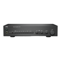
FRONT PANEL CONTROLS
1. POWER ON/OFF
Press
the PO\\'TR button to s$'itch the
pre-amplifief
t0 its Stand
.bl"
mode. The Stard-bv indicator
(No.
2) o\,er the
po\\'er
button
will
light up rurber On the fiont
panel, prcss
anv of the input
selector hutlons
t0 s\\itch to
pre
,unplifier on. lrom
üc
rc'note
control,
press
the
green
Stxnd-h\
butto0
(l0cated just
over the
Speakers A and B
buttons) to s$'itch the unit on. The
Stand-bv
irdicator will turn fiom amber to
grcen
t0
indicate
it is snitched
on and readv for usc.
REMOTE CONTROL
STAND-BY BUTTON
(GREEN)
Press thc Po$cr
butlon to s[itch the unit
on, thc Stand,by
irdicator on the frort
panel
rvill
tum fion anber to
green
wilhin
2 seconds, meanwhile
dle CD indicator automaticallv flashes
4
times . The unit is row readv lor
use
Nofri h Stand by mode thc
C160 uses ven little
pouer.
Ho\lever, it is recomrnencled
that
vou
swilch the
unit totallv off if
it is not
going
10 be used for more
then a couple ol da\s.
Switch
off
conldctcl]' by
pressing
the POWIR
hutton on the ftont
panel
(No.
l), all lights rvili
extinguish.
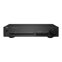
2. STAND-BY INDICATOR
The indicator
LED offe$ information
0n thc status of the trAl
cl60:
0ff:
Thc
unit is s$itched oil totally
,{mber The unit is ir
stand-bv mode
Greer: The unit is switched
on and
readv
for use.
l'he LID rvill ajso flash $hel
the
pre
mlplifier recejves
a
renote
control command fiom the
supplied
handset.
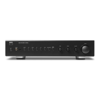
3.
HEADPHONE
SOCKET
A l/4' stereo
jack
s0ckct is supplied for headphonc listcning
and
$ill work \\ith conventional hcadphones
of any inpedancc.
lnsening
a
hcadphone
jack
into this socket amtomxticallv
switches
off the oulput to the l'Rt
OUT
i
& 2 sockets on üe back
paoel.
The voluorc,
tore and balance controls
are operatiye for
headphone listening.
LIsc a suitable adapter 10
conrcct
headphoncs
with other t\pes of sockcß,
such as
-l.5mm
stereo
'p€rsonal
sterco'
jzck
plugs.
1yOIf.' Listening
at
high
levels c,.n darnage
vour
hcaring.
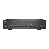
4. INFRA-RED REMOTE
CONTROL COMMAND
RECEIVER
The irirarcd
scnsor
located
behild this circuhr rvindoui
receives
con ands lion the remote
control. Thcrc nust be a clear line-
olsight
path
froor
the lemote control to this windo\!: if
that
pxth
is obstmct€d, the remote
control nlay trot \york.
 Loading...