Do you have a question about the NAD C740 and is the answer not in the manual?
Guidelines for replacing fuses with correct types for fire and shock prevention.
Procedures for ensuring insulation and safety before returning the unit to customers.
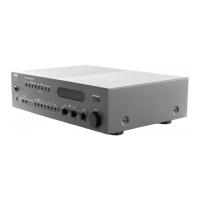
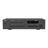
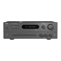
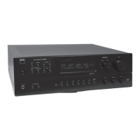
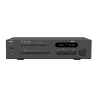
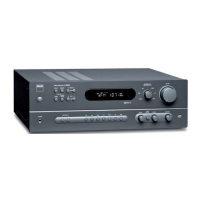
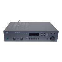
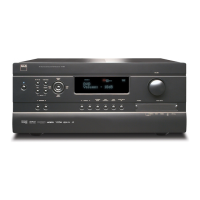
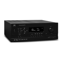
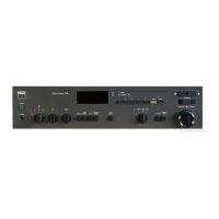
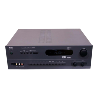
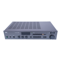
Identification and function of all controls on the front panel of the receiver.
Illustration and labeling of all input/output terminals on the rear panel.
Block diagrams showing instrument connections for FM and AM alignment procedures.
Detailed steps for aligning the FM and AM tuner sections using signal generators.
Procedure for adjusting idle current and offset voltage in the power amplifier stage.
Detailed pin description and terminal functions for the microprocessor.
| continuous average power output into 8Ω | 35W |
|---|---|
| clipping power (max continuous power per channel) | 40W |
| IHF dynamic power at 8Ω | 50W |
| IHF dynamic power at 4Ω | 90W |
| IHF dynamic power at 2Ω | 140W |
| usable input sensitivity FM Mono | 11.2 dBf |
|---|---|
| usable input sensitivity FM Stereo | 17.2 dBf |
| 50 dB quieting sensitivity FM Mono | 16.1 dBf |
| 50 dB quieting sensitivity FM Stereo | 36.1 dBf |
| capture ratio (FM) | 2.5 dB |
| harmonic distortion FM Mono | 0.1% |
| harmonic distortion FM Stereo | 0.15% |
| channel separation @1kHz | >45dB |
| frequency response | ± 1.5 dB 30Hz - 15 kHz |
| usable sensitivity | 10 mV |
|---|---|
| selectivity | 30 dB |
| IF rejection | 40 dB |
| signal / noise ratio | 40 dB |
| harmonic distortion | 0.7% |
| dimensions (W x H x D) | 17.125" x 3.375" x 11.5" (435 x 110 x 290mm) |
|---|---|
| net weight | 17.8lbs (8.1kg) |
| shipping weight | 20lbs (9.1kg) |