Do you have a question about the NAD 7020e and is the answer not in the manual?
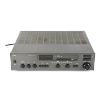
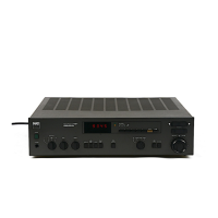
Identifies and describes rear panel inputs, outputs, and terminals for connectivity.
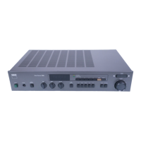
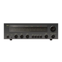
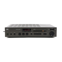
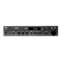
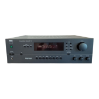
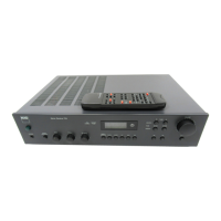
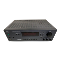
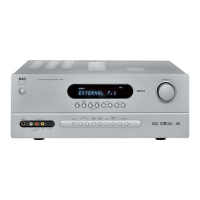
Identifies and describes front panel controls, buttons, and indicators.
Detailed technical performance data for the power amplifier section.
Technical details for the preamplifier, including phono and high-level inputs.
Technical performance data for the FM tuner section.
Dimensions, weight, power consumption, and power supply details.
Steps for initial calibration of center voltage and idling current.
Steps for final calibration after initial adjustments.
Lists test equipment required for FM tuning and alignment.
Procedure to check and adjust the oscillator tuning voltage.
Method for aligning RF tracking across frequencies.
Steps for coarse and final calibration of the FM detector.
Procedure to set the level for the autosearch function.
Calibration of stereo decoding and MPX filters.
Method to adjust stereo separation for optimal output.
Procedure for tuning the MPX filter for minimum output.
Procedure to adjust the AM oscillator circuit.
Steps for aligning the AM intermediate frequency stages.
Method for aligning the AM tuner's tracking.
The NAD 7220PE / 7020e AM/FM Receivers are designed to provide high-quality audio reproduction and versatile functionality for your home entertainment system. These receivers combine an amplifier and a tuner into a single unit, offering a comprehensive solution for listening to radio broadcasts and playing audio from various external sources.
The primary function of the NAD 7220PE / 7020e is to receive and amplify AM/FM radio signals, delivering clear and powerful audio to connected speakers. Beyond radio, the receiver acts as a central hub for multiple audio components. It features dedicated inputs for a turntable (Phono), CD player, video sound sources, and tape decks, allowing you to connect and switch between various devices effortlessly. The integrated amplifier ensures that the audio signals from these sources are boosted to a level suitable for driving your speakers, providing a rich and dynamic listening experience.
The NAD 7220PE / 7020e offers a user-friendly interface with a range of controls for tailoring your audio experience.
Front Panel Controls:
Rear Panel Connections:
The service manual provides detailed instructions for alignment and troubleshooting, indicating that the device is designed for professional servicing to ensure its longevity and optimal performance.
Alignment Method: The manual outlines specific alignment procedures for both the audio and tuner sections.
Parts List and Exploded View: The manual includes a comprehensive parts list and an exploded view diagram. These resources are invaluable for technicians, facilitating the identification and replacement of components during repair. The exploded view provides a visual guide to the internal structure of the receiver, showing how different parts fit together.
Schematic Diagrams and PCB Layouts: Detailed schematic diagrams for both the amplifier and tuner sections, along with PCB layouts, are provided. These diagrams illustrate the electronic circuitry and component placement, which are essential for diagnosing faults and performing repairs.
Overall, the NAD 7220PE / 7020e AM/FM Receivers are designed as robust and serviceable audio components, offering a blend of performance, versatility, and maintainability for enthusiasts and professionals alike.
| Tuning Range | FM, MW |
|---|---|
| Frequency Response | 20Hz - 20kHz |
| Input Sensitivity | 2.5mV (MM), 150mV (line) |
| Speaker Load Impedance | 4Ω to 16Ω |
| Power Output | 20 watts per channel into 8Ω (stereo) |