EasyManua.ls Logo

NAD 712 Service Manual

NAD 712
30 pages
To Next Page IconTo Next Page
Page #1 background imageLoading...
Page #1 background image
712
SERVICE
MANUAL
TUNER
SERVICE
SAFETY
PRECAUTIONS
(UL)
1,
Use
exact
replacement
parts
for
critical
locations
marked
/\*
2.
Return
lead
dress
to
original
position
and
re-install
protective
covers.
3.
Before
returning
to
customer,
test
for
shock
hazard;
use
either
mothod
A
or
B:
A.
Leakage
test
“cold”:
1.
Unplug
the
AC
cord;
turn
power
switch
ON.
2.
Connect
one
lead
of
High
Voltage
insulation
Tester
to
both
prongs
of
the
AC
plug.
3.
Touch
other
lead
to
all
exposed
metal
parts.
4,
Impedance
measurement
must
be
0.3-5.0
Megohms.
B.
Leakage
test,
“live”
:
1.
Plug
unit
directly
into
the
AC
outlet:
do
not
use
isolation
transformer.
2.
Connect
one
lead
of
the
Leakage
Current
Tester
to
earth
ground.
3.
Touch
other
lead
to
all
exposed
metal
parts.
4.
Leakage
measurement
must
be
less
than
0.5
milliamps.
AMPLIFIER

Other manuals for NAD 712

Question and Answer IconNeed help?

Do you have a question about the NAD 712 and is the answer not in the manual?

NAD 712 Specifications

General IconGeneral
Frequency Response20Hz to 20kHz
Total Harmonic Distortion0.03%
Damping Factor50
Input Sensitivity2.5mV (MM), 150mV (line)
Channel Separation50dB (line)
Speaker Load Impedance4Ω to 16Ω
Power Output25 watts per channel into 8Ω (stereo)

Summary

Service Safety Precautions

Leakage Testing Procedures

Details the 'cold' and 'live' leakage test methods.

Fuse Replacement and Safety Checks

Fuse Replacement Guidelines

Information on replacing fuses with correct types.

Post-Service Safety Check Procedure

Procedure for safety verification before customer release.

Technical Specifications

Power Amplifier Specifications

Detailed performance metrics for the power amplifier stage.

Preamplifier Section Specifications

Detailed performance metrics for the preamplifier stage.

FM and AM Tuner Performance

FM Tuner Sensitivity and Quieting Metrics

Usable sensitivity and quieting performance for FM signals.

AM Tuner Sensitivity and Signal-to-Noise

Usable sensitivity and S/N ratio for AM signals.

Front and Rear Panel Views

Front Panel Component Identification

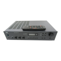
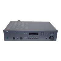
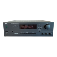
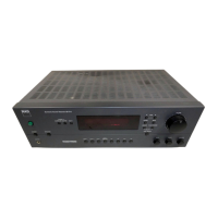
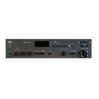
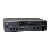
Labels and functions of the front panel controls and indicators.

Rear Panel Connection Layout

Identifies rear panel input/output connectors and terminals.

System Block Diagram and Signal Flow

Signal Flow Diagram Explanation

Illustrates the path of audio and control signals through the unit.

Power Supply Unit Design

Power Supply Circuitry Details

Breakdown of the power supply stages and voltage regulation.

Component Wiring Diagram

Disassembly Procedures

Removing the Top Cover

Step-by-step guide to removing the main enclosure cover.

Adjustment Point Diagrams

Tuner Board Adjustment Points

Identifies specific points on the tuner board for calibration.

Amplifier Adjustment Points

Identifies specific points for adjusting idle current in amplifier stages.

Alignment and Calibration Procedures

FM Section Alignment Procedures

Calibration steps for the FM tuner section.

IF and Synthesizer Alignment

Calibration for IF stages and synthesizer tracking.

RF, Auto-Search, and Stereo Alignment

Adjustments for RF, auto-search, stereo separation, and pilot suppression.

AM Section Alignment

Amplifier Adjustment Procedures

Output Offset Voltage Adjustment

Procedure to set zero DC offset at speaker terminals.

Idle Current Adjustment

Setting the quiescent current for amplifier output stages.

Final Amplifier Adjustments

Final checks and adjustments after initial setup.

PCB Layout Diagrams

AC, Motor Drive, and Speaker Terminal PCBs

Layouts for AC, Motor Drive, and Speaker Terminal boards.

Front Panel, Headphone, and Switch PCBs

Layouts for Front Panel, Headphone, and Switch PCBs.

Impedance, Antenna, and Other PCBs

Layouts for Impedance, Antenna, and other miscellaneous PCBs.

Front Panel Circuit Board Layout

Main and Tuner Board Layout

Power Supply and Mains Schematic

Input, Speaker, and Headphone Circuits

Input Jack and Selector Circuits

Schematics for various input connections and signal selection.

Speaker Output and Headphone Amplifier Circuits

Diagrams for speaker output terminals and headphone amplification.

Amplifier Circuit Schematics

Left and Right Channel Amplifier Stages

Detailed schematics for the main audio amplifier channels.

Front Panel and Motor Control Circuits

Front Panel Display and Control Logic

Schematics for front panel display, buttons, and control logic.

Motor Potentiometer and NAD Link

Circuits for motor-driven controls and NAD Link communication.

Integrated Circuit Block Diagrams

TC9163N, NJM072D, NJM2068 Diagrams

Block diagrams for key ICs used in signal processing and amplification.

LM7000 and LA1266 Block Diagrams

Block diagrams for tuner and FM/AM processing ICs.

TMS77C82 Microcontroller Block Diagram

Block diagram of the main microcontroller unit.

Additional IC Block Diagrams

LA3401 PLL MPX and MC14094BCP Diagrams

Block diagrams for PLL MPX and shift register ICs.

LB1642 Motor Driver and X24C01P EEPROM Diagrams

Block diagrams for motor driver and EEPROM ICs.

LC7582A LCD Driver Block Diagram

Block diagram for the LCD driver IC.

Exploded View Diagram

Exploded View Parts List - Chassis and Controls

Chassis, Panel, and Cover Components

List of parts for chassis, panels, and covers.

Knobs, Buttons, and Lenses List

List of knobs, buttons, and lens components.

Exploded View Parts List - Electronics and Hardware

Electronic Components and Connectors List

List of electronic components like PCBs, switches, and connectors.

Fasteners and Hardware List

List of screws, washers, and other hardware.

Exploded View Parts List (Continued)

Filters, Resistors, and Trimmers

List of filters, resistors, and trimmer potentiometers.

Fuses, Transformers, and Switches

List of fuses, transformers, and various switch types.

Specialized Components (Breakers, Resonators, Crystals)

List of breakers, resonators, crystals, and notes on critical parts.

Electrical Parts List - Assemblies and Components

Switch, Motor Pot, Headphone, Antenna, Lamp Assemblies

Lists electrical parts for various assemblies.

Capacitor, IC, Resistor, and Speaker Terminal Parts

Lists electrical parts for components and terminals.

Electrical Parts List - Mains, Diodes, and Passive Components

Mains Assembly, Diodes, and Capacitors

Lists mains assembly, diodes, and capacitors.

Resistors, Transistors, Relays, and Switches

Lists resistors, transistors, relays, and switches.

Electrical Parts List - Front Panel and Display Components

Front Panel Components, Diodes, and ICs

Lists front panel components, diodes, and ICs.

LCD Display and Transistors

Lists LCD display and transistors.

Electrical Parts List (Continued)

Switches and Tuner/Main Boards

Lists various switches and the main tuner/main circuit boards.

Capacitor Specifications and Types

Detailed list of capacitors with specifications and types.

Electrical Parts List (Continued)

Capacitor and Diode Components

Lists various capacitors and diodes with their part numbers.

Integrated Circuits (ICs) List

Lists all integrated circuits used in the unit.

Electrical Parts List (Continued)

Transistors and Diodes List

Lists transistors and diodes with their part numbers and specifications.

Resistors and Filters List

Lists resistors and filters with their specifications.

Electrical Parts List (Continued)

Resistors, Trimmers, and Breakers

Lists resistors, trimmer potentiometers, and breakers.

Fuses, Resonator, and Crystal

Lists fuses, resonator, and crystal components.

Packing Diagram

Packing List

Related product manuals