14
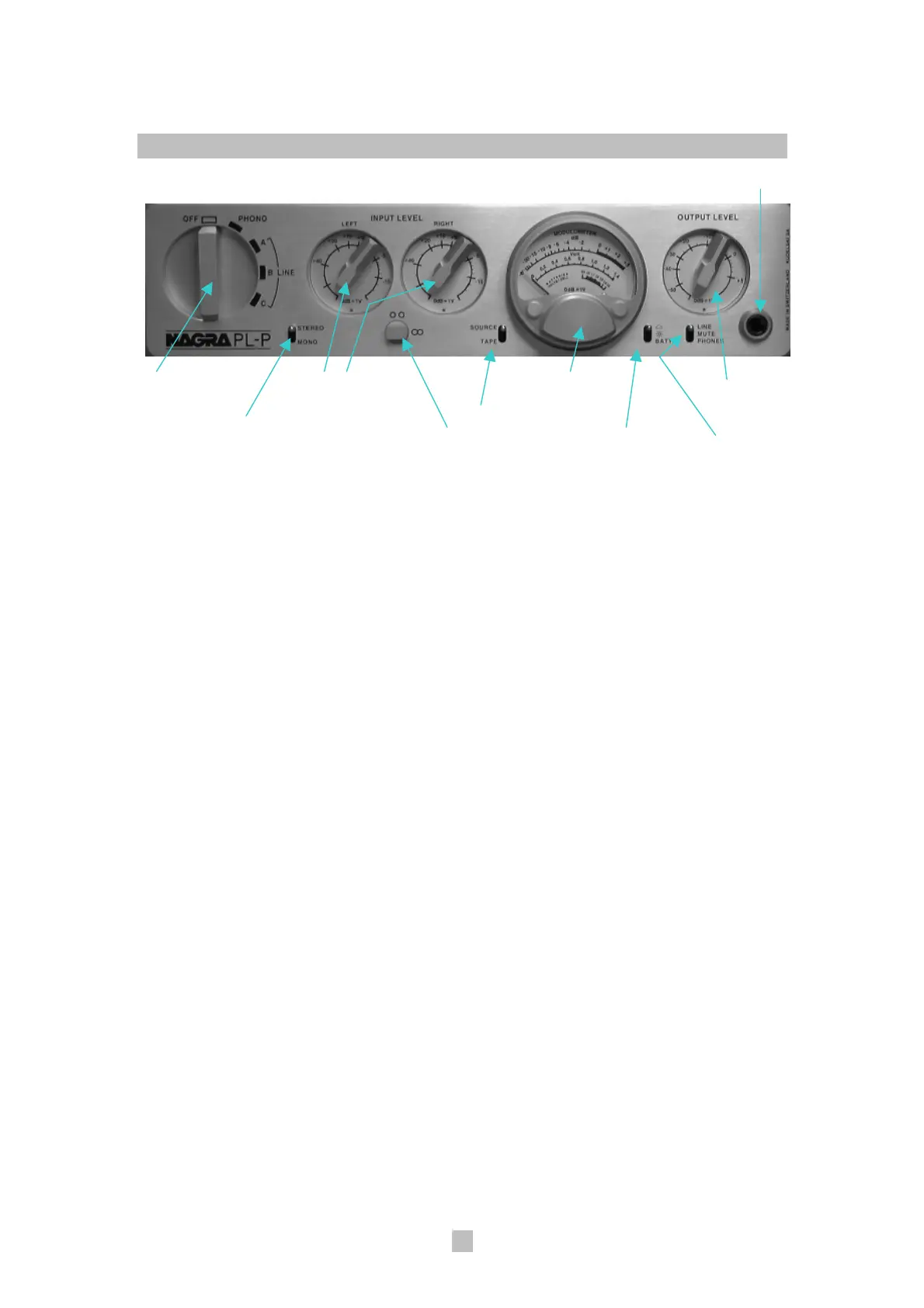
Front Panel/Control Layout
Headphone output connector
Main rotary switch Left & right Modulometer Output level
channel input potentiometer
level potentiometers Tape source
Mono/Stereo
selector switch Potentiometer Brightness/Battery Line/Phones
ganging clutch indication switch switch
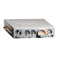
The front panel consists of a variety of controls and a modulometer. Starting
at the left of the front panel, they are:
1. The Main Rotary Switch
Powering the PL-P and input
selection is provided through the
main rotary switch on the left-hand
side of the front panel. This 5-
position rotary switch turns the PL-
P on and off as well as facilitates
selection of all input sources. The
positions of this main rotary switch
correspond with the following
labels, clockwise from top to
bottom:
• “OFF” - No power is supplied to
any audio stages. However, the
rechargeable power cell
management system is always
in operation and will draw less
than 3 mA. A red stripe is printed
on the backing plate in the space
occupied by the switch handle to
alert the user of having switched
the unit from the “OFF” position.
• “PHONO” - Power is supplied to
all active electronic stages. A 15-
second mute function engages
when the main rotary switchis
activated to this position to
eliminate unstable and surge
voltages at the output stage.
When switching between
“PHONO” and “LINE A”, a 3-
second mute will also be
activated.
• “LINE A”, “LINE B”, “LINE C” -
Power is supplied to line stage
active electronics and the
modulometer lamp (if switched
on) only. The phono stage
electronics will be turned off.
2. Mono/Stereo Switch
A toggle switch to the right of the
main rotary switch on the front
panel allows the selection of mono
or stereo operation.
 Loading...