Do you have a question about the Nakamichi 600II and is the answer not in the manual?
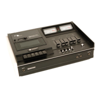
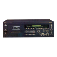
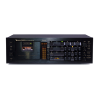
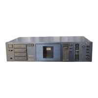
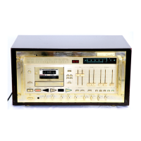
Identifies and explains the functions of the front panel controls.
Details the 2-head system and improvements for performance.
Explains the SuperHead technology and its impact on frequency response.
Describes headplate assembly and adjustments for tape guides and heads.
Procedure for removing the main cabinet.
Procedure for removing the main mechanism assembly.
Procedures for removing heads, pressure roller, and related parts.
Lists all instruments required for measurement and testing procedures.
Procedure to adjust take-up and rewind torque for proper tape handling.
Steps to adjust tape speed using a frequency counter and test tape.
Procedures for adjusting tape guides and heads for optimal alignment.
Procedure for adjusting the head base stroke for correct head positioning.
Adjusts motor pulley and checks belt travel for correct positioning.
Checks and adjusts mute and start switch movements in various modes.
Instructions for tape speed, tone calibration, meter levels, and head alignment.
Detailed procedures for adjusting playback and record frequency response.
Diagram and parts list for the Dolby NR PCB assembly.
Diagram and parts list for Calibration Board A (Cal. A P.C.B.).
Diagram and parts list for the Switch PCB assembly.
Diagram and parts list for the Power Supply PCB assembly.
Diagrams and parts lists for the Shut-off PCB (Hall IC and Reed Switch systems).
Overview of the synthesized assembly and its parts list.
Diagrams and parts lists for the chassis assembly (version 1/2).
Diagram and parts list for the 600II mechanism assembly (black version).
Diagram and parts list for the front control assembly.
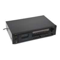
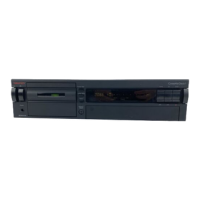
Diagram and parts list for the rear panel assembly.
Diagrams and parts lists for the mechanism assembly (version 1/2).
Diagrams and parts lists for the mechanism assembly (version 2/2).
Diagram and parts list for the cassette case assembly.
Diagrams and parts lists for the record/playback head assembly.
Graphs showing playback frequency response for different tape types and settings.
Schematic diagram for the amplifier section of the unit.
Schematic diagram for the mechanism control circuits.
Diagnoses common problems like distorted sound, poor frequency response, and playback failures.
Verification steps after replacing key components like motor or heads.
| power source voltage | 100, 120, 220, or 240 V |
|---|---|
| power source frequency | 50/60 Hz |
| power consumption | 15 W Max |
| tape speed | 1-7/8 ips (4.8 cm/sec) |
|---|---|
| wow and flutter | Less than 0.12% WTD Peak |
| frequency response | 35-20, 000 Hz +3 dB |
| signal to noise ratio | Better than 60 dB 400 Hz, 0 dB IHF-A WTD rms |
| total harmonic distortion | Less than 1.5% 400 Hz 0 dB |
| bias frequency | 105 kHz |
| input sensitivity | 50 mV, 50 k ohms |
|---|---|
| output level | 580 mV (400 Hz, 0 dB, Output Level at Max) |
| headphone output | 45 mW |
| dimensions | 15.75 (W) x 6.85 (H) x 9.41 (D) inches |
|---|---|
| dimensions in mm | 400 (W) x 174 (H) x 239 (D) mm |
| weight | 14.3 lbs (6.5 kg) |