3
WIRING
Connect the keypad wires to the control panel terminals shown in the table at the right.
KEYPAD ADDRESS JUMPERS
In summary, if more than one keypad is installed:
• Each must be assigned a unique address (that is, no two keypads may be numbered
alike).
•
Keypads must be addressed consecutively (that is, missing numbers are not permitted).
•
Only Keypad No. 1 may be used for programming. (However, for ease of programming, it
is recommended that a GEM-RP1CA / GEM-RP1CAe / GEM-RP1CAe2 be selected as
Keypad #1).
KEYPAD OPTION JUMPERS
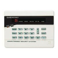
Up to 7 GEM-RP3DGTL keypads may be connected to the control panel (Keypads 1–7). Each must be configured for
a keypad address. In addition, the keypad may be configured to disable touchpad backlight and entry sounder.
Keypads are configured by the proper selection of jumpers. Refer to the label on the keypad circuit board for jumper
locations and a summary of settings.
JUMPERS:
A: DISABLE PUSHBUTTON BACKLIGHT
Cut Jumper A to disable touchpad pushbutton back-lighting.
C: DISABLE KEYPAD SOUNDER
Cut Jumper C to disable the keypad sounder. (Do not disable in UL Installations)
E: ENABLE KEYPAD TAMPER
Cut Jumper E to convert the keypad Chime LED to a system Tamper LED (only with control panels which support
system tamper).
COLOR TERMINAL
RED 9
BLACK 10
GREEN 11
YELLOW 12
WHITE* N/O PANIC
WHITE* N/O PANIC
* Cut and insulate 2 white
wires if not used.
KEYPAD
NUMBER
1 2 3 PARK
1 OFF or
ON
• •
2
•
ON
STORE SPARE
3 ON ON
JUMPERS
4
•
•
ON
IN THIS
5 ON
•
ON
POSITION
6
•
ON ON
7 ON ON ON
JUMPER SETTINGS
 Loading...