10 StarLink
™
SLE-LTE Commercial Series Alarm Communicators -- Installation Instructions
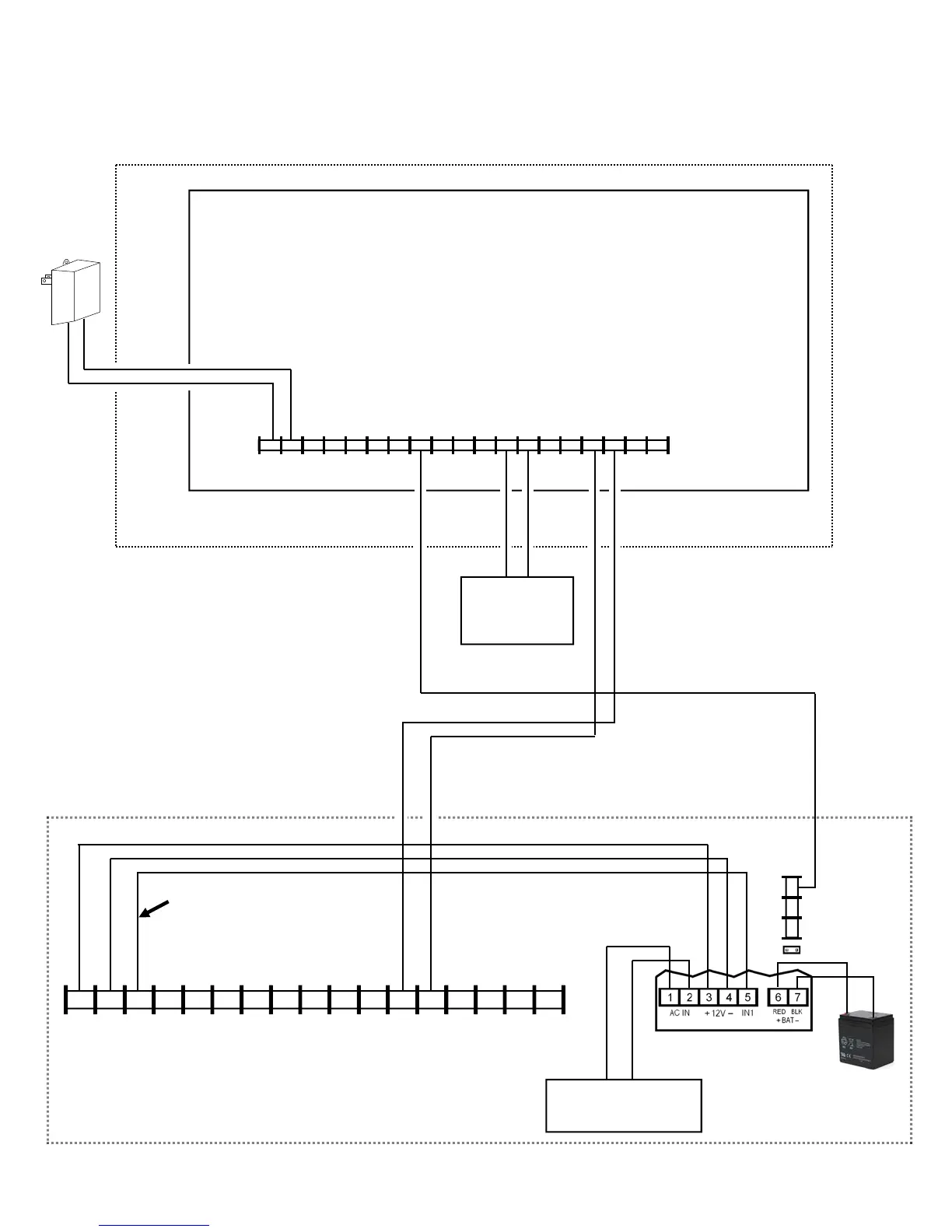
Wiring Diagram for PRIMARY Reporting Configuration
Generic Control Panels
(Use when telephone line is NOT available)
CONTROL PANEL PC BOARD
(CONTROL PANEL HOUSING)
*Refer to section "SUPPLYING POWER".
(–) (+)
12VDC
AUX POWER
(RING)
(TIP)
6 7 8 15 14 13 12 11 9 10 2* 3 4 5 1*
+V
(–)
PGM1 PGM2 PGM3 IN1 IN2 GND IN3 RING TIP
17 16
RTS
(R)
PANEL
TX (B)
PANEL
RX (G)
CTS
Y
StarLink Radio Terminals
PANEL
RING (+)
PANEL
TIP (–)
(–) (+)
(STARLINK RADIO HOUSING)
Power Supply (SLE-ULPS-R)
Either the TRF12/T123 (16.5V /
20VA) transformer or the chas-
sis-mounted 16.5VAC / 20VA
transformer
Transformer
(optional)
Optional: When Power
Supply SLE-ULPS-R is not
used, connect Panel Aux
Power to StarLink terminals
1 and 2 (observing polarity)
Wire to dedicated zone on the control
panel for Supervision when the Power
Supply board (SLE-ULPS-R) is not used.
SLE-LTEV-CB-TF PC Board: All connections
are power limited except AC Mains, Telco and
battery terminals. Terminals 14-17: No connec-
tions permitted.
StarLink
BATTERY
(+)
RED
(–)
BLACK
8 9 10
N/C
COM
N/O
J2
Note: Battery leads
are not power limited
TBL INPUT
GND
Note: Connect IN2 to a
panel output used for
identifying Telco line cut (this
is the DACT interconnect
wiring to the radio).