StarLink
™
SLE-LTE Commercial Series Alarm Communicators -- Installation Instructions 15
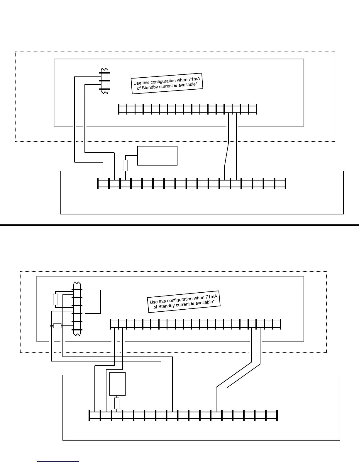
Wiring Diagram for PRIMARY Reporting Configuration
GEM-816 / GEM-P1632 / GEM-P1664 Control Panels
(Use when telephone line is NOT available)
(+) (–)
AUX POWER
5
6
13 14 15 16 17 18 19 20 21 22 26 27 28 29 23 24 25
Control Panel PC Board
~ ~
(un-polarized)
*Refer to section
"SUPPLYING
POWER".
TIP RING TIP RING
TELCO PHONE
(un-polarized)
6 7 8 15 14 13 12 11 9 10 2* 3 4 5 1*
+V
(–)
PGM1 PGM2 PGM3 IN1 IN2 GND IN3 RING
PANEL
RING
TIP
17 16
PANEL
TIP
RTS
(R)
PANEL
TX (B)
PANEL
RX (G)
StarLink Radio Terminals
~ ~
(un-polarized)
CTS
Y
2.2K
ZONE (+)
DEDICATED TO
SUPERVISION
CTS
Y
6 7 8 15 14 13 12 11 9 10 2* 3 4 5 1*
+V
(–)
PGM1 PGM2 PGM3 IN1 IN2 GND IN3 RING
PANEL
RING
TIP
17 16
PANEL
TIP
RTS
(R)
PANEL
TX (B)
PANEL
RX (G)
StarLink Radio Terminals
~ ~
(un-polarized)
Wiring Diagram for PRIMARY Reporting Configuration
GEM-X255 / GEM-P9600 / GEM-P3200 Control Panels
(Use when telephone line is NOT available)
(+) (–)
AUX POWER
(CONTROL PANEL HOUSING)
13 14 15 16 17 18 19 20 21 22 26 27 28 29 23 24 25 33 30 31 32
Control Panel PC Board
~
(un-polarized)
~
*Refer to section
"SUPPLYING
POWER".
TIP RING TIP RING
TEL LINE PHONE
ZONE (+)
DEDICATED TO
SUPERVISION
2.2K
(un-polarized)
SLE-LTEV-CB-TF PC
Board: All connec-
tions are power lim-
ited except AC
Mains, Telco and
battery terminals.
Terminals 14-17: No
connections permit-
ted.
SLE-LTEV-CB-TF
PC Board: All con-
nections are power
limited except AC
Mains, Telco and
battery terminals.
Terminals 14-17:
No connections
permitted.
6
7
8
AUX RELAY
(Cut Jumper A)
COM
N/C
N/O
10K
(CONTROL PANEL HOUSING)
9
10
10K
Note: Connect
IN2 to a panel
output used for
identifying Telco
line cut (this is the
DACT interconnect
wiring to the radio).
Note: Connect IN2 to a
panel output used for
identifying Telco line cut (this
is the DACT interconnect
wiring to the radio).