W415-1146 / A / 02.16.13
26
EN
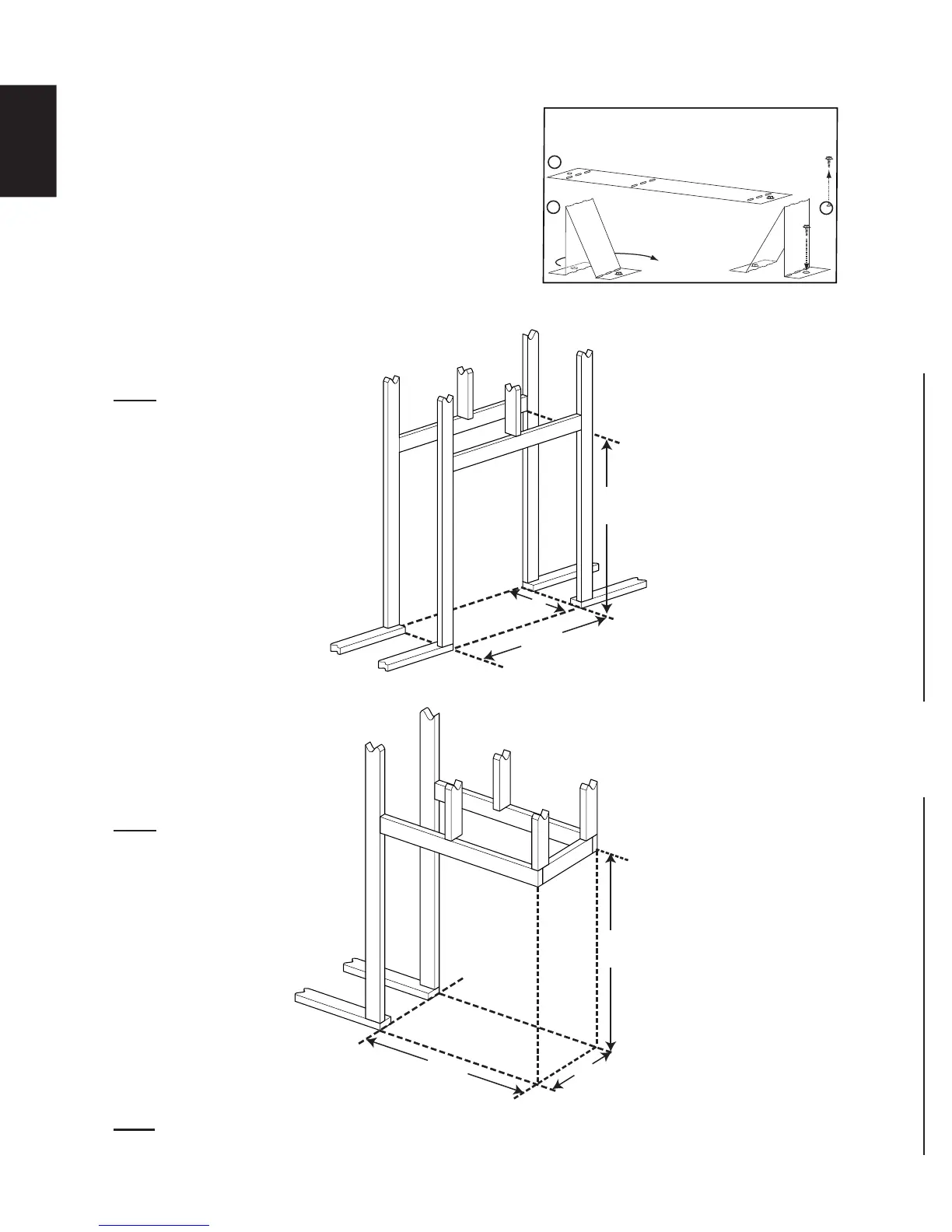
* When constructing the enclosure allow for fi nishing material thickness to maintain clearances.
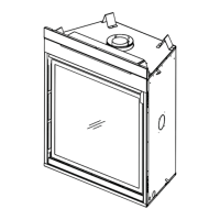
STAND-OFFS
Bend and secure the stand-offs as
illustrated
:
A
B
C
This appliance is supplied with four stand-offs. For
convenience the stand-offs have been shipped fl at and
located on the top of the appliance. Before framing
ensure the stand-offs are bent up and screwed into
place ensuring a height of 10" (254mm). Stand-offs are
not used for structural support
42
1
/2
”
(1079.5mm)
40
3
/4
”
(1035.1mm)
A
42
1
/2
”
(1079.5mm)
A
38
3
/8
”
(974.7mm)
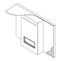
5.1 FRAMING
5.1.1 SEE-THRU FRAMING
5.1.2 PENINSULA FRAMING
NOTE: Dimension "A" should
measure 17 5/8" (447.7mm)
minimum (depending on the
fi nishing material thickness)
NOTE: Dimension "A" should
measure 17 5/8" (447.7mm)
minimum (depending on the
fi nishing material thickness)
NOTE: All framing dimensions are based on the fi nishing material supports position. Framing may change
depending on the fi nishing material thickness. (See "FINISHING SUPPORT ADJUSTMENT" section).
 Loading...