© National Instruments | 6-1
6
Digital Routing and Clock
Generation
This chapter describes the digital routing and clock routing circuitry on the cDAQ controller.
Digital Routing
The digital routing circuitry has the following functions:
• Manages the flow of data between the bus interface and the acquisition/generation
sub-systems (analog input, analog output, digital I/O, and the counters). The digital routing
circuitry uses FIFOs (if present) in each sub-system to ensure efficient data movement.
• Routes timing and control signals. The acquisition/generation sub-systems use these
signals to manage acquisitions and generations. These signals can come from the following
sources:
– Your C Series modules
– User input through the PFI terminals using parallel digital C Series modules
• Routes and generates the main clock signals for the cDAQ controller. To determine the
signal routing options for C Series module(s) installed in the cDAQ controller, refer to the
Device Routes tab in MAX.
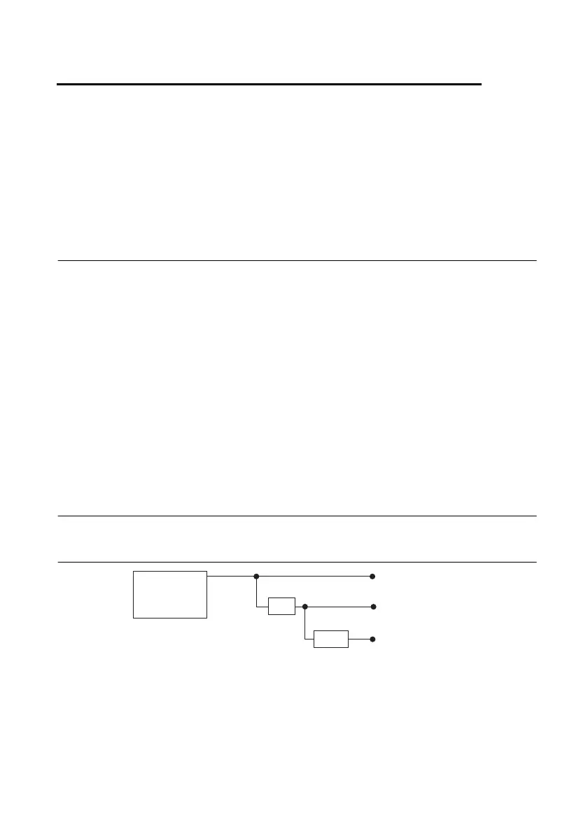
Clock Routing
Figure 6-1 shows the clock routing circuitry of the cDAQ controller.
Figure 6-1. Clock Routing Circuitry
¹ 4
¹ 200
80 MHz Timebase
100 kHz Timebase
20 MHz Timebase
80 MHz
Timebase