© National Instruments | 1-37
NI cDAQ-9132/9133/9134/9135/9136/9137 User Manual
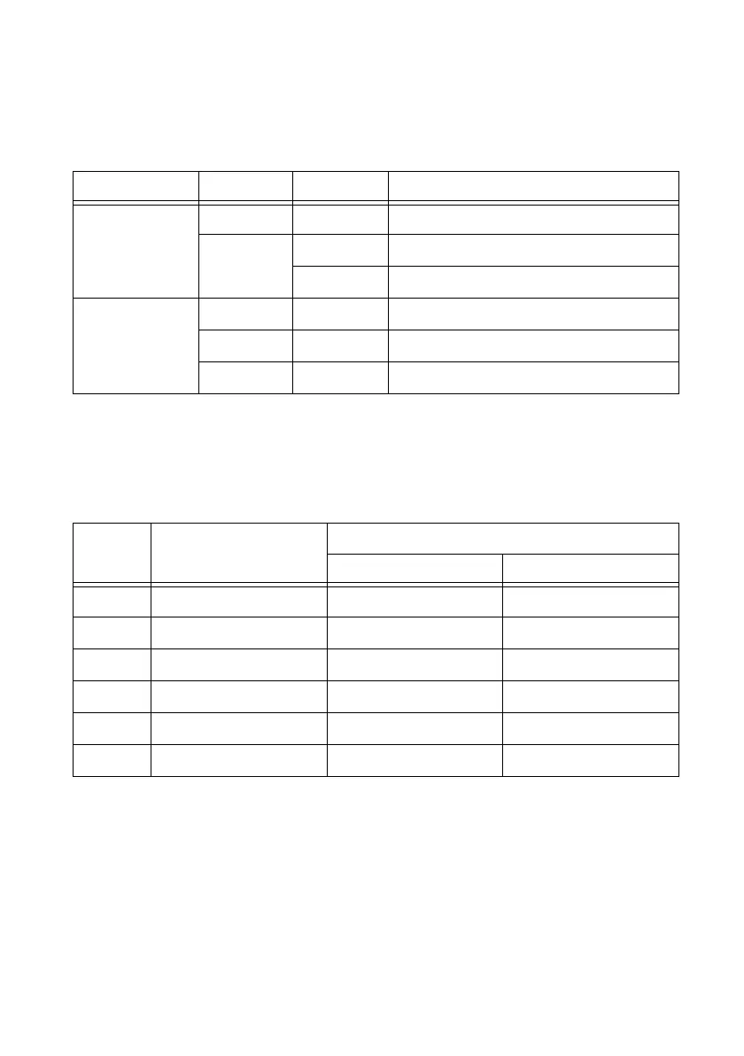
Ethernet LEDs
Each Ethernet port has two LEDs—ACT/LINK and 10/100/1000—described in Table 1-7.
Ethernet Cabling
Table 1-8 shows the shielded Ethernet cable wiring connections for both straight through and
crossover cables.
Table 1-7. Ethernet LED Indications
LED LED Color LED State Indication
ACT/LINK — Off LAN link not established
Green Solid LAN link established
Flashing Activity on LAN
10/100/1000 Ye ll ow Solid 1,000 Mbit/s data rate selected
Green Solid 100 Mbit/s data rate selected
— Off 10 Mbit/s data rate selected
Table 1-8. Ethernet Cable Wiring Connections
Pin Connector 1
Connector 2
Straight Through Crossover
1 white/orange white/orange white/green
2 orange orange green
3 white/green white/green white/orange
4 blue blue blue
5 white/blue white/blue white/blue
6 green green orange
 Loading...