3-2 | ni.com
Chapter 3 Counters
counter sample clock. You can route an external signal or one of many different internal signals
as the sample clock. For example, you can generate a signal using one counter and route that
signal to the sample clock of another counter. Refer to Chapter 5,
Counter Signal Routing and
Clock Generation
, for more information about which signals can be used as the source.
Counter Input Applications
The following sections list the various counter input applications available:
• Edge Counting
•
Pulse Measurement
• Semi-Period Measurement
• Frequency Measurement
• Period Measurement
• Pulse-Width Measurement
• Two-Edge Separation
Edge Counting
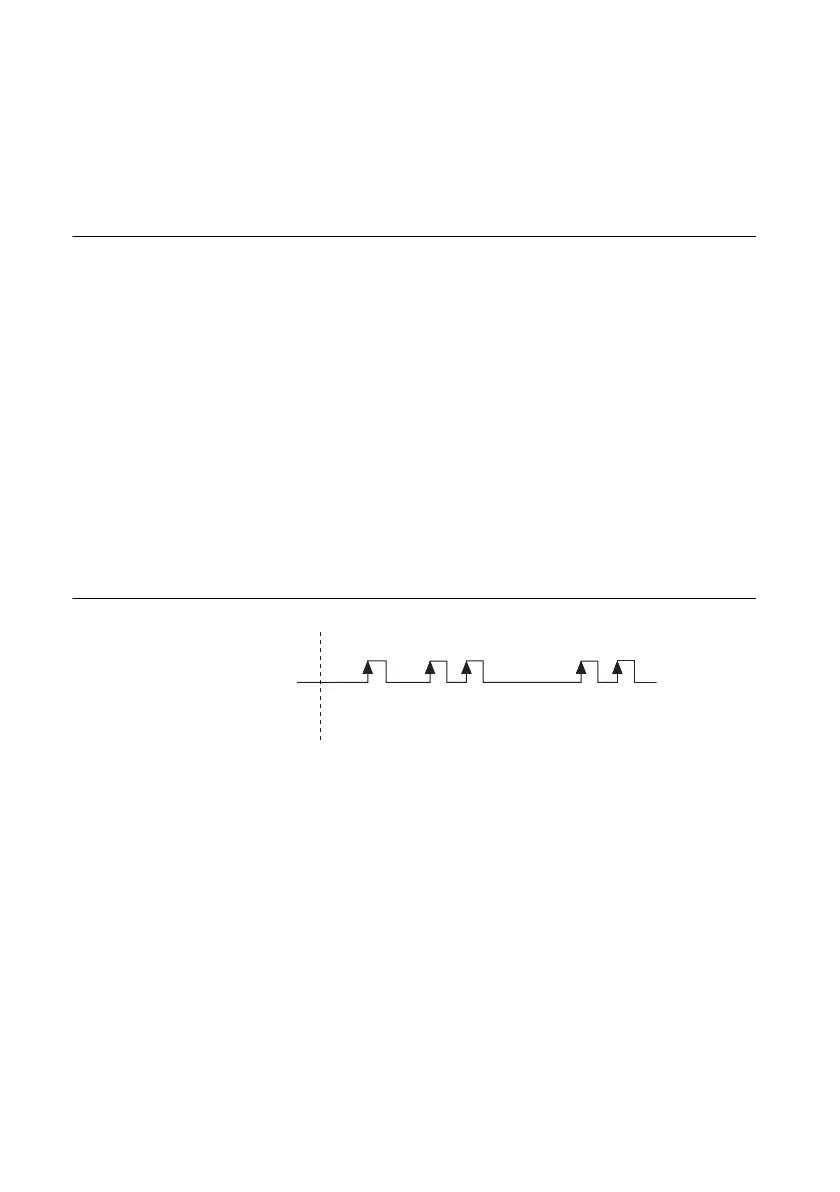
In an Edge Counting measurement task, the counter counts the number of active edges of a
signal. Figure 3-2 shows an example of edge counting.
Figure 3-2. Edge Counting
Channel Settings
By default, the counter:
• starts the count at 0.
• counts edges on a default PFI terminal. Refer to Chapter 5, Counter Signal Routing and
Clock Generation
, for more information.
• counts rising edges.
• counts up always.
You can change these behaviors by configuring DAQmx Channel properties:
• CI.CountEdges.InitialCnt—To specify the initial value of the count.
• CI.CountEdges.Term—The signal-to-measure comes from an input terminal. To change
the signal-to-measure, specify a different terminal via this property.
Start Task
Signal to Measure
Count 105432
 Loading...


