3-36 | ni.com
Chapter 3 Counters
Generating Complex Digital Waveform or Timing
Pattern
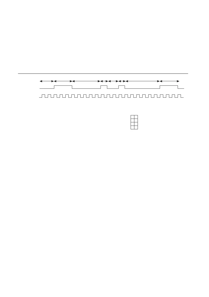
A complex digital waveform or timing patterns consists of a series of pulses. Each pulse consists
of an idle time and active time. To specify the waveform, create a buffer with multiple points.
Each point consists of the idle time and active time of one pulse of the waveform.
Figure 3-41 shows an example of creating a buffer to describe a waveform.
Figure 3-41. Complex Digital Waveform
You can specify the points in the waveform buffer in terms of:
•Time
• Ticks of the timebase clock (10 ns by default)
• Frequency and duty cycle
Create Channel
Use one of the following functions to create a channel. Select the VI or function that corresponds
to the format of the data in the waveform buffer:
• DAQmx Create Channel (CO Pulse-Generation Time)
• DAQmx Create Channel (CO Pulse-Generation Ticks)
• DAQmx Create Channel (CO Pulse-Generation Frequency)
Channel Settings
By default, the counter outputs the pulses on a default PFI terminal. Refer to Chapter 5,
Counter
Signal Routing and Clock Generation
, for more information
You can change the output terminal by using the CO.Pulse.Term DAQmx Channel property.
Output
Counter
Timebase
2
Buffer
2
3
5
2
6
1
1
3
Sample
1
2
3
4
Idle Ticks
2
5
2
6
Active Ticks
3
1
1
3
3 5 1 2 1 6 3
 Loading...


