© National Instruments Corporation 15 NI USB-6008/6009 User Guide and Specifications
Connecting a signal greater than ±10 V on either pin results in a clipped output.
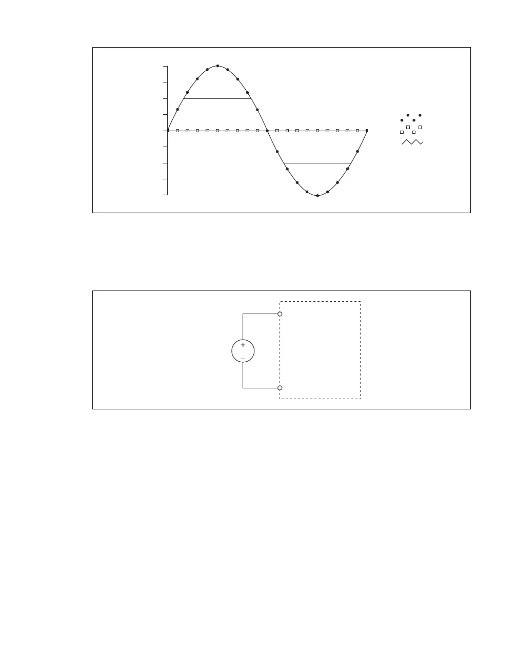
Figure 10. Exceeding ±10 V on AI Returns Clipped Output
Taking Referenced Single-Ended Measurements
To connect referenced single-ended (RSE) voltage signals to the NI USB-6008/6009, connect the
positive voltage signal to an AI terminal, and the ground signal to a GND terminal, as shown in
Figure 11.
Figure 11. Connecting a Referenced Single-Ended Voltage Signal
When no signals are connected to the analog input terminal, the internal resistor divider may cause the
terminal to float to approximately 1.4 V when the analog input terminal is configured as RSE. This
behavior is normal and does not affect the measurement when a signal is connected.
Digital Trigger
You can configure PFI 0 as a digital trigger input for analog input tasks. Refer to the Using PFI 0 as a
Digital Trigger section for more information.
–5
–10
–15
–20
20
15
10
5
0
Amplitude (V)
AI 1
AI 5
Result
AI
NI USB-6008/6009
GND
Voltage
Source

 Loading...


