NI VirtualBench Calibration Procedure | © National Instruments | 63
8. Call PS Read Output with the following parameter:
• Channel =
ps/+6V
9. Subtract the DMM reading from step 7 from the DC power supply Actual Current Level
reading in step 8. Verify that calculation falls between the limits in Table 22 or 23.
10. Repeat steps 5 through 9 for each verification point on this channel.
11. Call
PS Reset Instrument.
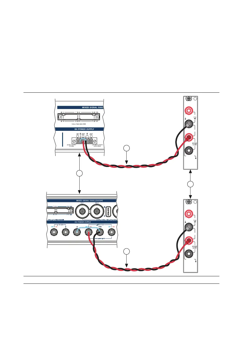
12. Disconnect all connections and connect Channel +25 V to Amps HI, and Common Floating
GND to Amps LO as shown in Figure 33. Connect GND and Common Floating GND with
a jumper.
Figure 33. Cable Connections For +25 V Current Programming Accuracy Verification
13. Repeat steps 5 through 11 for the ps/+25V channel.
1 VirtualBench DC Power Supply 2DMM 3 Cabling Wire
1
3
3
2
HI
LO
300V
MAX
AMPS
500V MAX
HI
LO
1kV
MAX
3A, 250V
MAX
INPUT
MAX
1kV
HI
LO
300V
MAX
AMPS
500V MAX
HI
LO
1kV
MAX
3A, 250V
MAX
INPUT
MAX
1kV
 Loading...