8 | ni.com | NI VirtualBench Calibration Procedure
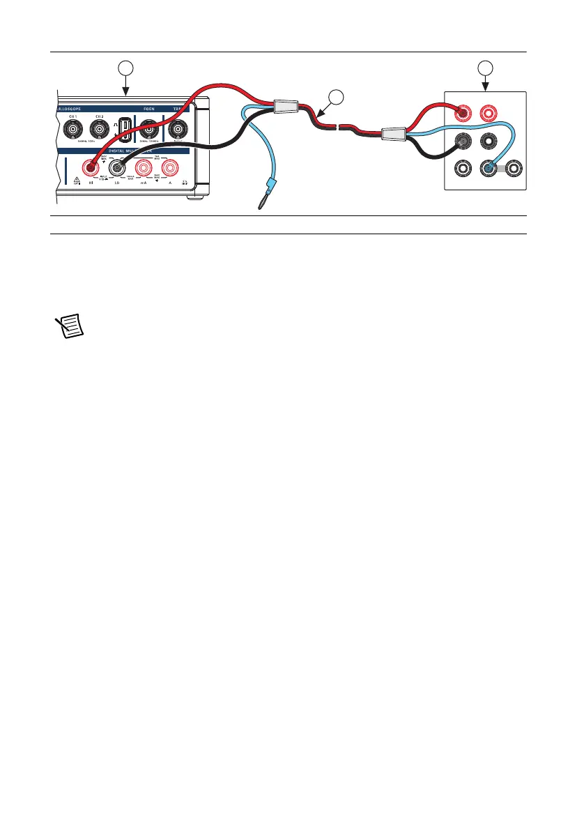
Figure 1. Cable Connections for DC Voltage
3. Wait 2 minutes for the thermal EMF to stabilize.
4. Null the points by completing the following steps:
a. For the 100 mV range, set the calibrator to 0 V.
Note When outputting less than 220 mV, range lock the calibrator to 2.2 V so it
prevents creating a voltage divider with the internal resistance of the VirtualBench.
b. Call
DMM Configure Measurement with the following parameters:
• Function = DC Volts
• Auto Range = FALSE
• Manual Range = 0.1
c. Set the input resistance of the VirtualBench to 10 GΩ by calling DMM Configure
DC Voltage
with the following parameter:
• Input Resistance =
10 GOhm
d. Call DMM Read. Record this measurement.
5. Generate 0.101 V verification point on the calibrator.
6. Call
DMM Configure Measurement with the following parameters:
• Function = DC Volts
• Auto Range = FALSE
• Manual Range = 0.1
7. Set the input resistance of the VirtualBench to 10 GΩ by calling DMM Configure DC
Voltage
with the following parameter:
• Input Resistance = 10 GOhm
1 VirtualBench DMM 2 Multifunction Calibrator 3 Low EMF Copper Cable
HI
LO
HI
LO
HVI
SENSE
VΩ
OUTPUT
VΩA
AUX
CURRENT
GUARD GROUND
3
1 2
 Loading...