NI VirtualBench Calibration Procedure | © National Instruments | 9
8. Call DMM Read. Subtract the saved value from step 4 and compare to the limits listed in
Table 4.
Note Use the values in the 24 Hour Limits column for a post-adjustment
verification only. Otherwise, use the values in the 1 Year Limits column.
9. Repeat steps 5 through 8 for each verification point listed for the 100 mV range in Table 4.
10. Generate 1.01 V verification point on the calibrator.
11. Call
DMM Configure Measurement with the following parameters:
• Function =
DC Volts
• Auto Range = FALSE
• Manual Range = 1
12. Set the input resistance of the VirtualBench by calling DMM Configure DC Voltage
with the following parameter:
• Input Resistance = 10 GOhm
13. Call DMM Read. Compare to the limits listed in Table 4.
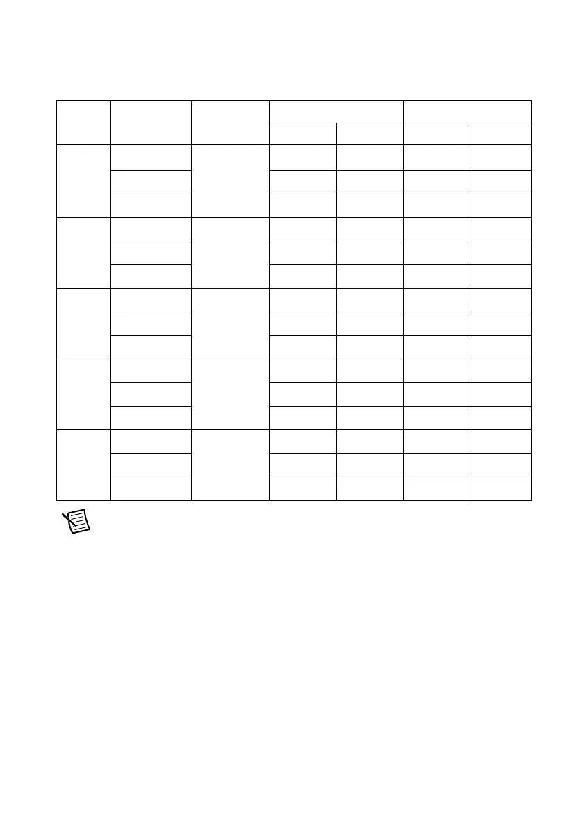
Table 4. VirtualBench DC Voltage Verification Limits
Range
(V)
Verification
Point (V)
Input
Resistance
1 Year Limits (V) 24 Hour Limits (V)
Lower Upper Lower Upper
0.1 0.101 10 GΩ 0.100980 0.101020 0.100996 0.101004
0 -0.000005 0.000005 -0.000003 0.000003
-0.101 -0.101020 -0.100980 -0.101004 -0.100996
1 1.01 10 GΩ 1.009800 1.010200 1.009960 1.010040
0 -0.00005 0.00005 -0.00002 0.00002
-1.01 -1.010200 -1.009800 -1.010040 -1.009960
10 10.1 10 GΩ 10.0980 10.1020 10.0997 10.1003
0 -0.0005 0.0005 -0.0002 0.0002
-10.1 -10.1020 -10.0980 -10.1003 -10.0997
100 101 10 MΩ 100.960 101.040 100.993 101.007
0 -0.005 0.005 -0.002 0.002
-101 -101.040 -100.960 -101.007 -100.993
300 150 10 MΩ 149.933 150.068 149.979 150.021
0 -0.015 0.015 -0.014 0.014
-150 -150.068 -149.933 -150.021 -149.979
 Loading...