NV30/NV40 Operations and Maintenance Manual Description
Page 1-4 Issue 3.3 2014-12-10
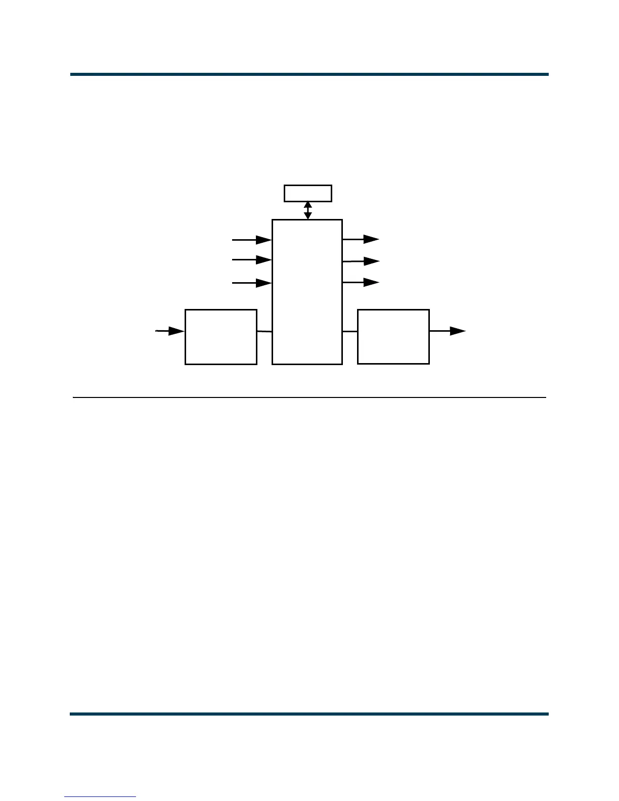
The control/interface PWB contains push-button switches that provide backup control for the RF
on/off, local/remote, power increase/decrease and reset functions. It also contains LEDs that serve
as an alternate means to monitor status (local/remote and RF on/off), forward power level
(percentage indicators from 10% to 100% of maximum RF output power) and various alarms.
Figure 1.1: Control/Monitor Stage
RF drive stage
See Figure SD-6. The RF drive stage converts the exciter's RF output to the intermediate RF level
needed to drive the RF power modules. It consists of exciter A (A3), exciter B (A4, optional) and RF
drive splitter/changeover assembly (A5).
Exciter(s)
Refer to the functional block diagram: NVE300 Exciter Block Diagram - see page 1-10.
Exciters A (A3) and B (A4) are the RF drive sources for the transmitter. They accept the external
audio program and/or IBOC information (see the NV30/NV40 Installation Manual for details on
various program input types). The exciters’ main/standby operation is controlled locally using the
AUI, or remotely. The exciter outputs are applied to the RF drive splitter/changeover assembly (A5).
The exciter provides an RF drive signal of 130 W (in analog mode).
From RF Power Stage
From Ac-Dc Power Stage
AUI
To RF Power Stage
To Ac-Dc Power Stage
Control/
Interface
PWB
To RF Drive Stage
From RF Drive Stage
From Remote
Controller
To Remote
Monitor
(part of)
Remote
Interface
PWB
(part of)
Remote
Interface
PWB
 Loading...


