NV30/NV40 Operations and Maintenance Manual Operating the transmitter
Page 2-52 Issue 3.3 2014-12-10
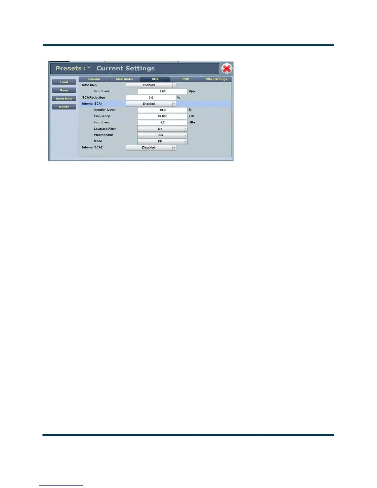
Figure 2.37: Presets - SCA
SCA - (see Figure 2.37)
:
• MPX SCA Connector (J7:A for SCA1, J7:B for SCA2) for use with an externally gen-
erated SCA; select Enabled or Disabled. When enabled, all the selections
listed below are active.
– Input Level: signal level that represents 10% modulation. Enter a value
between 1 and 5 V p-p (typically 2.83 Vpp).
• SCA Reduction Attenuation applied to the SCA input; set between 0 and 20% (used to
reduce the modulation level of the main audio when SCAs are enabled;
typically, for every 2% of SCA modulation, the main audio modulation
must be reduced by 1%).
• Internal SCA1/2 Enable or disable the appropriate internal SCA (SCA1 or SCA2). When
enabled, the settings listed below are active for the associated SCA signal
(1 or 2).
– SCA1 or SCA2 Injection Level: enter value between 0 and 20% (typically
10%); this level is added to the composite baseband signal.
– SCA1 or SCA2 Frequency: enter value between 20 and 100 kHz (typically
set to 67 kHz or 92 kHz).
–SCA1 or SCA 2 Input Level: enter value between -12 and +12 dBu, which
represents the input voltage level that yields 10% modulation (typically
4.7 dBu).
 Loading...


