2.5.3 Connecting Power
Connect the power cable to a 12 VDC or 24 VDC power supply, capable of supplying 2A peak to the
DC power lead (red = positive, black = negative) and plug the power connector into the Nauticast
B2. Please see the Appendix B of this manual for details of the power, data and RF cables supplied.
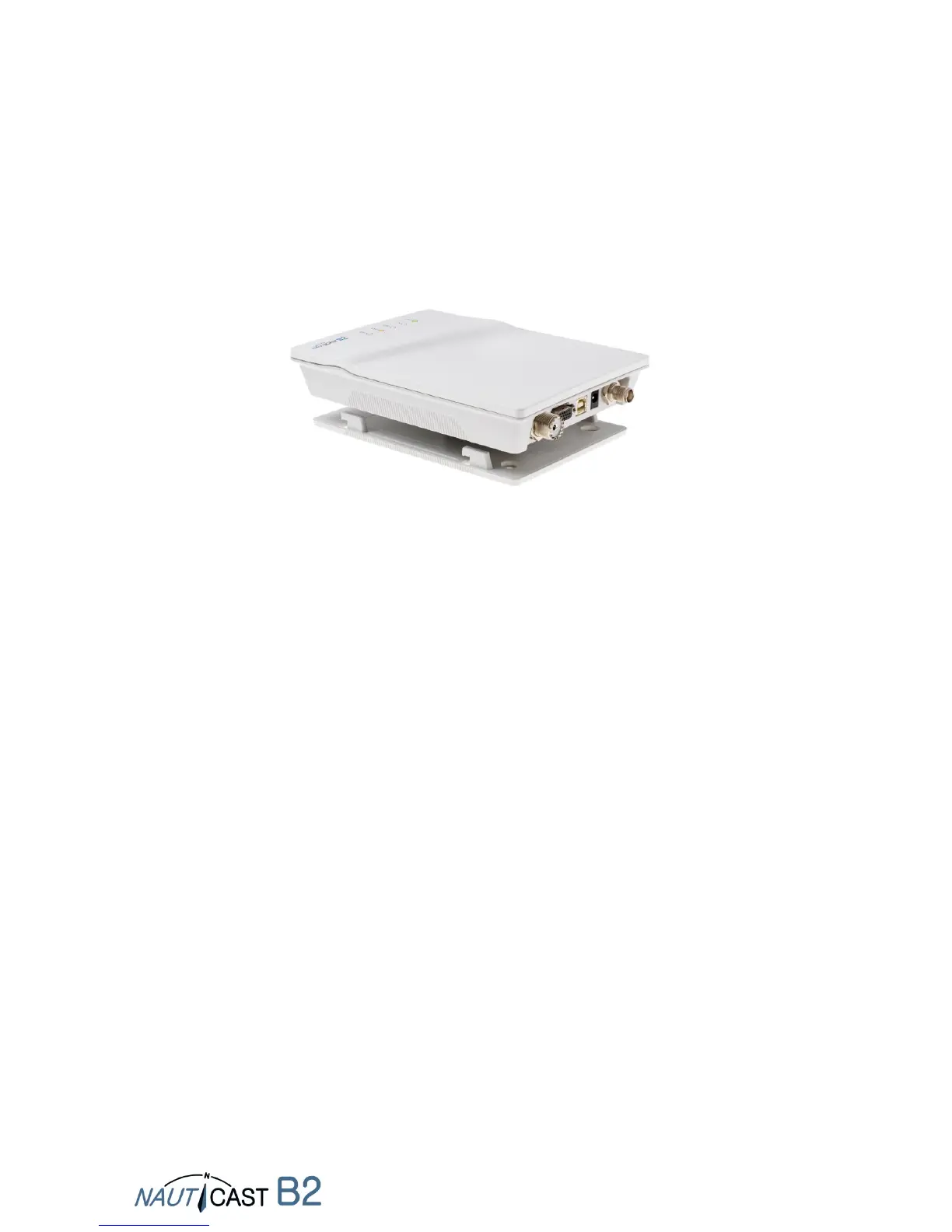
2.5.4 Mounting the Nauticast B2
Attach the mounting plate with Phillips self tapping head screws (10-32 x 1,2) on a vertical surface.
Please see Appendix C for the mounting plate’s exact dimensions.
Then insert the Nauticast B2 main unit and press down firmly until it snaps in.
2.5.5 Installation Check
You now have successfully completed the installation of your Nauticast B2 AIS system. After
connecting the main power supply allow the system 5 minutes to calibrate and start operation.
Then check the LED status. Normal operation is indicated by:
PWR: green (note: LED will be a dimmer shade of green on USB power supply as well)
However, USB-only power supply is NOT sufficient for full operation,
so make sure 12-24VDC main power is actually supplied!
TX: off
ERR: off
CH1, CH2: blinking green, amber or red
(when actual transmissions occur, dark in between transmissions)
When you encounter a different behaviour please consult section 4 Operation of your Nauticast B2.