11
NFB(commercial)
CH1 CH2 CH3
NULTI SW FLOW SW
EXIT INPUT TEMPERATURE SENSOR
LP SW
OUT DOOR DHW TANK
0~10V IN 0~10V OUT
(+)
(-)
(+)
(-)
SYSTEM
SUPPLY
SYSTEM
RETURN
R W
T/S ZONE 1 T/S ZONE 2 T/S ZONE 3
C
R W
C
R W
C
R W
C
T/S DHW
3.LWCO
2.AC24VL
1.AC24VN
CNK1
You can remotely control and monitor boilers, water heaters, or cascade
systems by connecting them to NaviLink communication channels
(CH1–CH3) and setting parameters on the front panel of boilers or water
heaters.
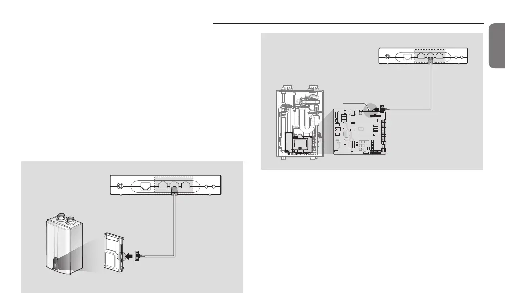
Connecting to a single boiler/water heater
You can connect the NaviLink and a boiler or water heater via the
NaviLink cable.
1
Connect the RS-485 connector of the NaviLink cable to a
communication channel port.
2
Connect the 5 pin connector of the NaviLink cable to the J6 port on
the right side of the boiler or water heater front panel or to the CNK1
port of the controller.
Connecting to boilers/water heaters
 Loading...