17
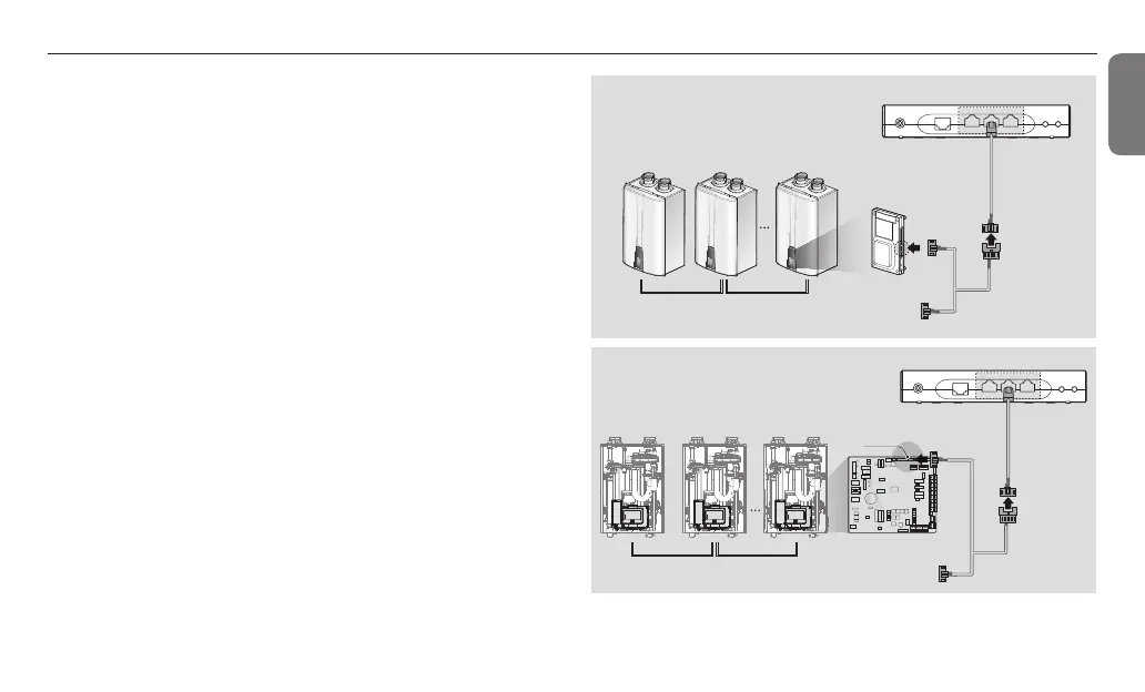
NPE/NHB Cascade System
A
B
C
NULTI SW FLOW SW
EXIT INPUT TEMPERATURE SENSOR
LP SW
OUT DOOR DHW TANK
0~10V IN 0~10V OUT
(+)
(-)
(+)
(-)
SYSTEM
SUPPLY
SYSTEM
RETURN
R W
T/S ZONE 1 T/S ZONE 2 T/S ZONE 3
C
R W
C
R W
C
R W
C
T/S DHW
3.LWCO
2.AC24VL
1.AC24VN
NFB(commercial) Cascade System
A
C
CNK1
B
Connecting to a cascade system
You can remotely control and monitor cascade systems by connecting
them to NaviLink communication channels (CH1–CH3). To connect the
NaviLink to a cascade system, a Navien Ready-Link cable (optional) and
NaviLink cable should be connected.
1
Connect the RS-485 connector of the NaviLink cable to a
communication channel port.
2
Connect the 5-pin connector of the NaviLink cable to connector A of
the Navien Ready-Link cable.
3
Connect the connector B of the Navien Ready-Link cable to the J6
port on the right side of the main unit panel or to the CNK1 port of
the controller.
4
Connect connector C of the Navien Ready-Link cable to another
Navien Ready-Link cable connected to a sub unit.
 Loading...