35Installing the System Piping
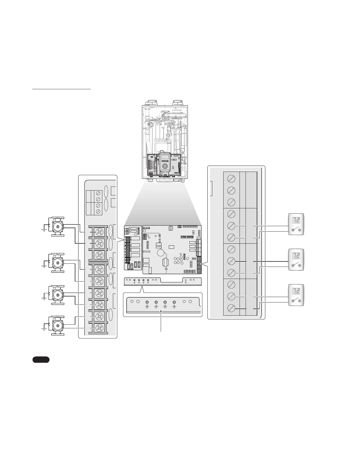
3.6.3 Wiring Diagram - Zone Pump System
The NFB Boilers can operate a heating system with up to 3 zones. The following is the wiring diagram for a zone pump system with 3 zones.
Without 24VAC connections
COM
A/H DHW PRI
NO
NC N L N L
N
L
COM
NO
NC
ZONE1
COM
NO
NC
ZONE2
COM
NO
NC
ZONE3
AC24VN
SUPPLY RETURN OUTDOOR DHW TANK
AC24VL
LWCO
R
W
C
R
W
C
R
W
C
R
W
C
COM
A/H
DHW PRI
NO NC N L N L N L
Zone pump 1
(max. 2.5 A)
Zone pump 2
(max. 2.5 A)
Zone pump 3
Boiler pump
(max. 2.5 A)
LWCO
AC24VL
AC24VN
NC
COM
ZONE3
COM
NC
NC
ZONE3
AC24VN
SUPPLY RETURN OUTDOOR DHW TANK
AC24VL
LWCO
R
W
C
R
W
C
R
W
C
R
W
C
Thermostat 3
Pump Ground
Note
●
If you have a 24 V thermostat, connect it to the R & C terminals on the boiler’s PCB.
●
The C terminals are for optional connections with 24 V thermostat COMMON.
 Loading...