About the Boiler 39
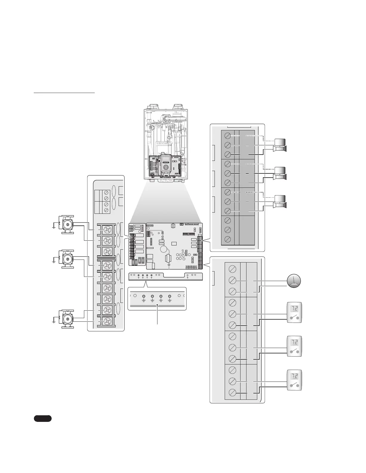
3.6.5 Wiring Diagram - Zone Valve System
The NFB Boilers can operate a heating system with up to 3 zones. The following is the wiring diagram for a zone valve system with 3 zones.
Without 24VAC connections
COM
A/H DHWPRI
NO
NC N L N L
N
L
COM
NO
NC
ZONE1
COM
NO
NC
ZONE2
COM
NO
NC
ZONE3
AC24VN
SUPPLY RETURN OUTDOOR DHW TANK
AC24VL
LWCO
R
W
C
R
W
C
R
W
C
R
W
C
System pump
(max. 2.5 A)
COM
A/H
DHW PRI
NO NC N L N L N L
DHW pump
(max. 2.5 A)
Boiler pump
(max. 2.5 A)
Pump Ground
NC
NC
COM
NC
NC
COM
LWCO
AC24VL
AC24VN
NC
NC
COM
ZONE1ZONE2ZONE3
COM
NC
NC
ZONE1
COM
NC
NC
ZONE2
COM
NC
NC
ZONE3
AC24VN
SUPPLY RETURN OUTDOOR DHW TANK
AC24VL
LWCO
R
W
C
R
W
C
R
W
C
R
W
C
Thermostat 1
Thermostat Input
24 VAC L
DHW Aquastat
(priority)
Thermostat 2
Thermostat Input
24 VAC L
Thermostat 3
Thermostat Input
24 VAC L
COM
NC
NC
COM
LWCO
AC24VL
AC24VN
NC
NC
COM
ZONE2ZONE3
COM
NO
NC
ZONE1
COM
NO
NC
ZONE2
COM
NO
NC
ZONE3
AC24VN
SUPPLY RETURN OUTDOOR DHW TANK
AC24VL
LWCO
Zone
valve 1
Zone
valve 2
Zone
valve 3
Note
●
NO (Normal Open): Power is supplied when the zone valve is operating, and power turns off when the zone valve stops.
●
NC (Normal Close): Power is supplied when the zone valve stops, and power turns off when the zone valve is operating.
●
COM: 24 V AC COMMON
 Loading...