About the Boiler 43
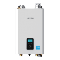
3.6.9 Wiring Diagram - Air Handler
COM
NO
NC
ZONE1
COM
NO
NC
ZONE2
COM
NO
NC
ZONE3
AC24VN
SUPPLY RETURN OUTDOOR DHW TANK
AC24VL
LWCO
R
W
C
R
W
C
R
W
C
R
W
C
COM
A/H DHWPRI
NO NC N L N L
N
L
SUPPLY RETURN OUTDOOR DHW TANK
R
W
C
R
W
C
COM
A/H DHW PRI
NO
<Air Handler>
R
W
C
R
W
C
<NFB>
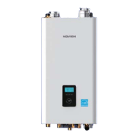
If you are using the navien manifold system, connect the pump
wires to the system pump. If you are not using the navien manifold
system, connect the pump wires to either the system pump or the
boiler pump.
<NFB>
System Pump
(max. 2.5 A)
Boiler Pump
(max. 2.5 A)
COM
NO
NC
ZONE1
COM
NO
NC
ZONE2
COM
NO
NC
ZONE3
AC24VN
SUPPLY RETURN OUTDOOR DHW TANK
AC24VL
LWCO
R
W
C
R
W
C
R
W
C
R
W
C
COM
A/H DHW PRI
NO NC N L N L
N
L
COM NO NC N L N L
N
L
Pump Ground
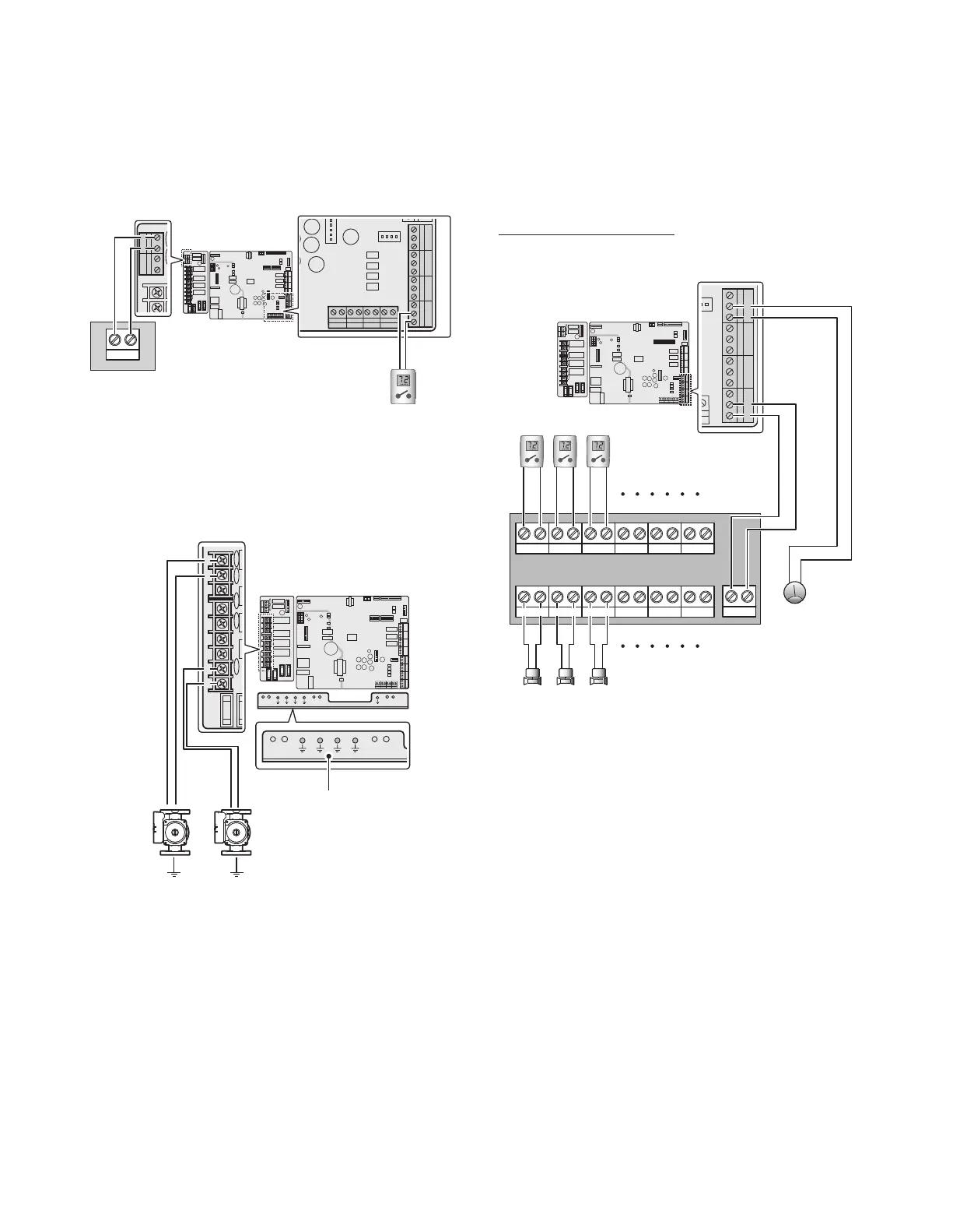
3.6.10 Wiring Diagram - DHW System with Indirect
Tank
When connecting the Aquastat
<Aquastat>
<NFB>
COM
NO
NC
ZONE1
COM
NO
NC
ZONE2
COM
NO
NC
ZONE3
AC24VN
SUPPLY RETURN OUTDOOR DHW TANK
AC24VL
LWCO
R
W
C
R
W
C
R
W
C
R
W
C
COM
A/H DHW PRI
NO NC N L N L
N
L
AC24VN
SUPPLY RETURN OUTDOOR DHW TANK
R
W
C
R
W
C
R
W
C
R
W
C
Zone1 T/S Zone2 T/S Zone3 T/S Zone4 T/S Zone5 T/S
Zone6 T/S
Zone1 Valve Zone2 Valve Zone3 Valve Zone4 Valve Zone5 Valve Zone6 Valve
T/T
Generic Zone Controller

 Loading...