DIAGNOSTICMANUAL
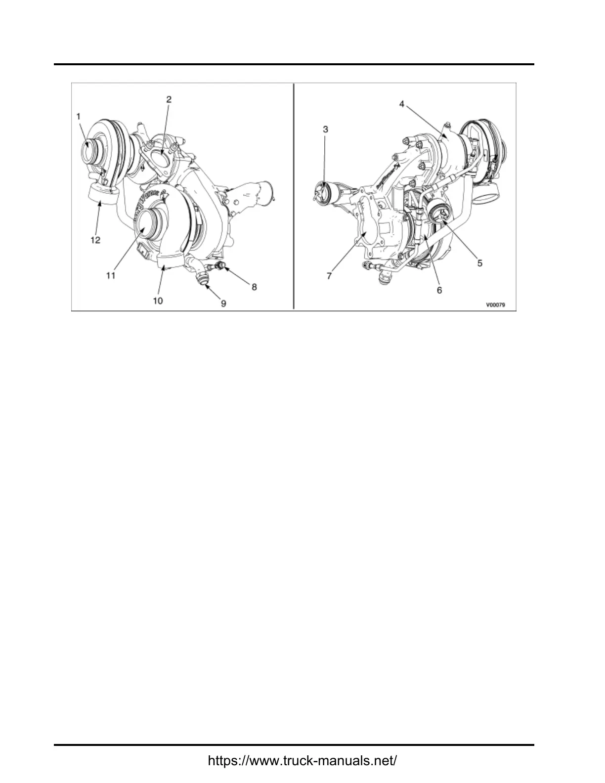
1.HPturbochargercompressorinlet
2.HPturbochargerturbineinlet
3.LPturbochargerwastegate
actuator
4.HPturbocharger
5.HPturbochargerwastegate
actuator
6.LPturbocharger
7.LPturbochargerturbineoutlet
8.Oilsupplyline
9.Oilreturnline
10.LPturbochargercompressor
outlet
11.LPturbochargercompressorinlet
12.HPturbochargercompressor
outlet
Figure43HighandLowPressureTurbochargerComponents—InnerandOuterViews(MaxxForce®
11and13Engines)
Turbochargers
MaxxForce®11and13enginesareequippedwithapneumaticallyregulatedtwo-stageturbochargingsystem.
TheHPandLPturbochargersareinstalledontherightsideoftheengine.
Intakeairow:FilteredairenterstheLPcompressor,whereitiscompressedanddirectedtotheLPCAC
(ifequipped).CooledLPairenterstheHPcompressorwhereitisfurthercompressedanddirectedintothe
HPCAC.CompressedairthentravelsthroughtheETVandtheintakethrottleduct.Thissystemprovideshigh
chargeairpressuretoimproveengineperformanceandtohelpreduceemissions.
Exhaustgasow:TheHPturbochargerisconnecteddirectlytotheexhaustmanifoldthroughtheHPturbine
inlet.ExhaustgasesexittheHPturbineoutletandaredirectedtotheLPturbineinlet.TheHPandLP
turbochargersareequippedwithwastegates,whicharecontrolledbypneumaticactuators.Whenboost
demandislow,thewastegateisopened,allowingpartoftheexhaustgasowtobypasstheturbine.
146
https://www.truck-manuals.net/
 Loading...


