8
Inputs
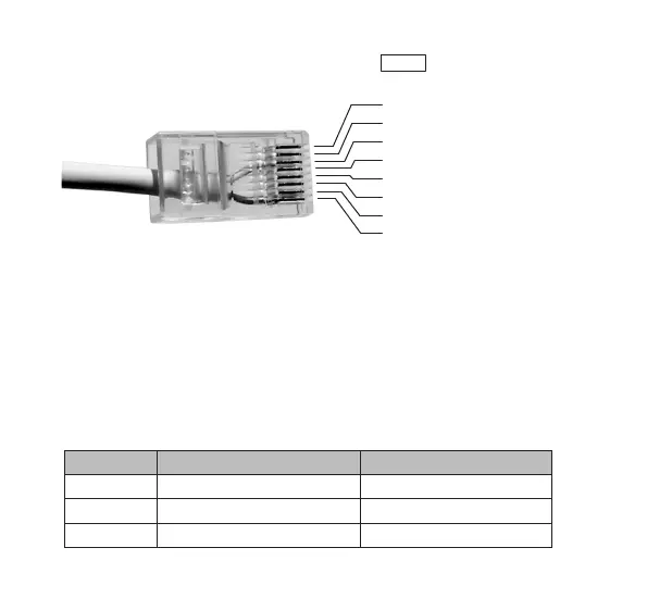
The inputs are connected to the jack marked
IN
. The pin layout is
shown in the picture below.
Input 1 is connected between pin 3 and 8, input 2 between pin 4 and
8, etc.
Inputs 1-3 may be configured either as normally open or normally
closed. Inputs 4-5 are always configured as normally open. If input 1 is
configured as normally open, an alarm will be sent when pin 3 is tied to
pin 8. If input 1 is configured as normally closed, an alarm will be sent
when the connection between pin 3 and pin 8 is broken.
Jumpers J1-J3 inside the IOR determine the mode of inputs 1-3 as
shown in the table below.
Jumper ON (mounted) OFF (not mounted)
J1 Input 1 normally closed Input 1 normally open
J2 Input 2 normally closed Input 2 normally open
J3 Input 3 normally closed Input 3 normally open
1. DC +5-9V output
2. DC +3V output
3. Input 1
4. Input 2
5. Input 3
6. Input 4
7. Input 5
8. Ground