EasyManuals Logo
Home>NEC>Monitor>AccuSync LCD71VM

NEC AccuSync LCD71VM User Manual

NEC AccuSync LCD71VM
129 pages
To Next Page IconTo Next Page
To Previous Page IconTo Previous Page
Page #94 background imageLoading...
Page #94 background image
6-6
4. Abnormal Screen
NG
NG
OK
OK
Check the R, G, B video signal from compute
r
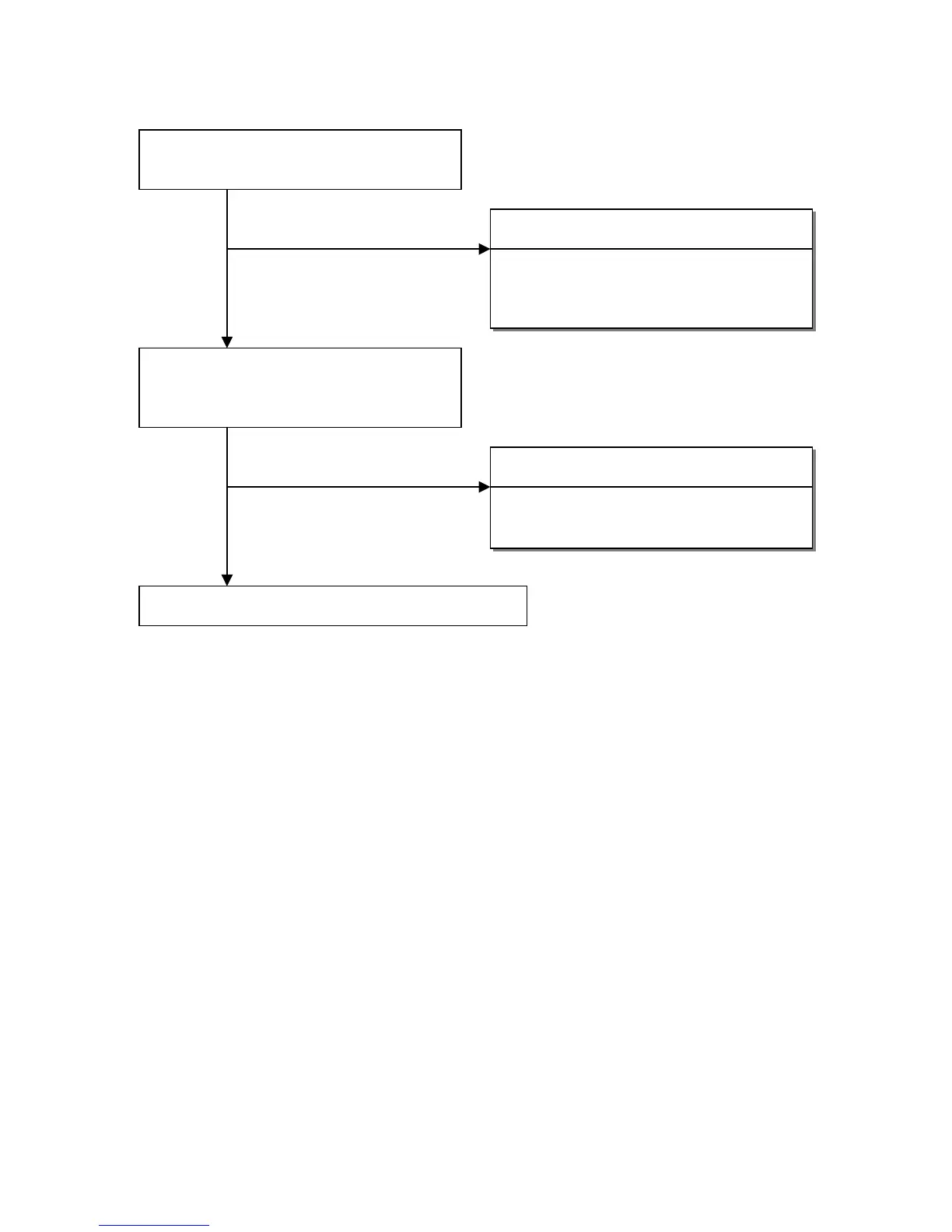
input on D-Sub R,G,B connector.
Failure point
1) No R, G and B video signal output from hos
t
computer. Check computer.
2) Video signal cable disconnection.
Check the R,B,G input signals on U405 pins
135, 131, 127,respectively that their level is
0.7Vp-p typical.
Failure point
Printed wire broke between D-Sub(R,G,B) and
U405 pins 135,131,127.
Proceed section 7 “Checking the scaling IC movement”.

Table of Contents

Other manuals for NEC AccuSync LCD71VM

Questions and Answers:

Question and Answer IconNeed help?

Do you have a question about the NEC AccuSync LCD71VM and is the answer not in the manual?

NEC AccuSync LCD71VM Specifications

General IconGeneral
BrandNEC
ModelAccuSync LCD71VM
CategoryMonitor
LanguageEnglish

Related product manuals