EasyManua.ls Logo

NEC MultiSync LCD1550ME - User Manual

NEC MultiSync LCD1550ME
131 pages
Print Icon
To Next Page IconTo Next Page
Loading...
COLOR MONITOR
MultiSync
LCD1550ME
MODELS LCD1550ME (B) / -BK(B)
200206
08EK1ABD
08EK2ABD
SERVICE MANUAL
PART NO. 599910589
NEC-MITSUBISHI ELECTRIC VISUAL SYSTEMS CORPORATION
JUNE 2002

Table of Contents

Questions and Answers

  • A
    Anna RamosAug 13, 2025
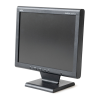
    How to fix a black screen on my NEC MultiSync LCD1550ME with an amber LED?
    • C
      Catherine DavisAug 13, 2025
      If your NEC monitor screen is black and the LED shows an amber light, ensure the computer is sending a sync signal to the monitor. If not, try changing the cable. Also, you may need to check the resolution change IC movement as described in the relevant section.
  • K
    Kathy SilvaAug 16, 2025
    How to troubleshoot no power on issue on NEC MultiSync LCD1550ME?
    • J
      Joseph GonzalezAug 16, 2025
      If your NEC monitor isn't powering on, start by inspecting components like F801, D801, and P801, and repair them if needed. Also, check R805, R803, ZD802, Q801, and I801, and their surrounding components such as Q805 and Q806. Further checks should include Q803, R813, R814, D806, R812, D804, R807, and the feedback circuit around I802 and I803, repairing where necessary.
  • L
    Lisa RothAug 20, 2025
    What to do if nothing displays on the NEC Monitor screen, but the LED is green?
    • T
      Tracey FlemingAug 20, 2025
      If your NEC monitor screen is black but the LED shows a green light, several issues could be the cause. First, check the video cable for any damage or loose connections; reconnect or replace it if necessary. You might also want to try changing the video signal output pattern on your computer. If these steps don't resolve the issue, consult the "Abnormal screen" section for further troubleshooting.
  • S
    Stephanie GardnerAug 25, 2025
    What to do if the plug and play operation on my NEC monitor is abnormal?
    • D
      David WaltonAug 25, 2025
      If the plug and play operation of your NEC monitor is not working correctly, confirm the input of serial clock on I308 pin 6 SCL at TTL level and confirm the input of serial data on I308 pin 5 SDA at TTL level. The video cable may have failed or may not have connections for DDC.
  • P
    Patricia WatsonAug 28, 2025
    How to check the audio circuit on NEC monitor?
    • R
      Rachel ByrdAug 28, 2025
      If you are experiencing issues with the audio circuit on your NEC monitor, first, check the audio cable for any disconnections. Also, verify that the setup of the host PC hasn't been altered.
  • R
    robin39Aug 31, 2025
    How to fix no OSD display on NEC monitor?
    • V
      vanessa09Aug 31, 2025
      If there's no OSD (On-Screen Display) showing on your NEC monitor, proceed with the steps described in the "Checking the resolution change IC movement" section.
  • C
    Casey HawkinsSep 4, 2025
    How do I check the DC/DC converter circuit on my NEC monitor?
    • S
      Stephanie CollinsSep 4, 2025
      If you're checking the DC/DC converter circuit in your NEC monitor, verify that the printed wire is intact between I310 pin 3 and the output of FB321, and also between I310 pin 2 and the I306 power supply pin.
  • B
    Bethany NicholsSep 8, 2025
    How to check the CPU operation on NEC monitor?
    • D
      Devin CarterSep 8, 2025
      If you are checking the operation of CPU on your NEC monitor and suspect an X301 failure, ensure that the input of the 5V "H" pulse from I303 pin 4 matches I302 pin 7, which should typically be around 14 milliseconds.

Summary

Safety Precautions and Warnings

General WARNING

Essential safety information for service personnel regarding training and procedures.

PRODUCT SAFETY CAUTIONS

Guidelines for safe servicing, component replacement, and tool usage.

Important Safety Information

Fire and Shock Hazard Warnings

Precautions against fire, shock hazards, and proper polarized plug usage.

Electrical Shock and Servicing Cautions

Warnings about electric shock, user-serviceable parts, and handling.

Quick Start Guide

Connecting the Monitor

Step-by-step instructions for connecting the LCD monitor to a computer system.

Monitor Installation and Mounting

On-Screen Manager (OSM) Controls

OSM Button Functions and Menus

Explanation of OSM button functions and basic menu navigation.

Image Adjustment Controls

Using OSM for contrast, auto adjust, position, and color settings.

OSM Tool Functions and Information

OSM options for positioning, turn-off, lockout, notifier, and factory preset.

Recommended Use and Ergonomics

Setup and Usage Safety Precautions

Guidelines for optimal setup, usage, and maintenance to prevent hazards.

Ergonomic Placement and Viewing

Adjusting monitor height, distance, and angle for user comfort.

Monitor Specifications

Display and Input Specifications

Technical details on LCD module, resolution, colors, and input signals.

Troubleshooting Common Issues

No Picture Diagnosis

Diagnostic steps for screens that are black or have amber LED indicators.

Abnormal Image Display Issues

Diagnosing and fixing unstable, unfocused, or improperly sized images.

No OSM Display Troubleshooting

Steps to diagnose and resolve issues with no OSM display.

Serial Number Information

Disassembly Procedures

Initial Disassembly Steps

Instructions for removing covers and cables before disassembly.

Adjustment Procedures

Service Mode Entry

Steps required to enter the service mode for factory adjustments.

Input Video Signal Settings

VG-819 settings for various input video signal modes.

VIDEO Gain Adjustments

Procedure for adjusting video gain and confirming display quality.

Inspection Procedures

VG-819 Signal Settings Tables

Tables detailing VG-819 settings for various signal modes.

Input Signal Identification

Verifying correct display for each signal input type.

Pre-shipment Procedures and Safety Tests

External Inspection

System Configuration and Data Inspection

Writing and Inspection Procedures

Writing model/serial data and confirming OSM information.

Troubleshooting

No Display (Amber LED)

Diagnostic flowchart for screen blackness with amber LED.

Nothing Displays (Green LED)

Diagnostic flowchart for no display with green LED.

Backlight Unit Checks

Diagnostic steps for the backlight unit and inverter.

Abnormal Screen Diagnosis

Flowcharts for diagnosing abnormal screen conditions.

No OSM Display Diagnosis

Steps to diagnose and resolve issues with no OSM display.

Resolution Change IC Movement

Diagnostic steps for resolution change IC functionality.

No Power On (Part 1)

Initial troubleshooting steps for power-on failures.

No Power On (Part 2)

Further troubleshooting for power-on failures.

DC;DC Converter Circuit Check

Diagnostic steps for the DC/DC converter circuit.

CPU Operation Check

Diagnostic steps for CPU operation and related components.

Audio Circuit Check

Diagnostic steps for the audio circuit and connections.

Inverter Board Circuit Check

Diagnostic steps for the inverter board circuits.

Circuit Description

Inverter Circuit

Replacement Parts List

Integrated Circuits (ICs)

List of IC components with part numbers and descriptions.

Transistors

List of transistor components with part numbers and descriptions.

Diodes

List of diode components with part numbers and descriptions.

Capacitors

List of capacitor components with part numbers and descriptions.

Block Diagram

LCD1550 ME Main Block Diagram

Overall block diagram illustrating the monitor's main functional units.

Schematic Diagrams

Interface PWB (Microcontroller;Key Function)

Schematic for the microcontroller and key function interface.

Power PWB Schematic

Complete schematic diagram of the power PWB.

Inverter PWB Schematic

Schematic diagram for the inverter PWB.

NEC MultiSync LCD1550ME Specifications

General IconGeneral
BrandNEC
ModelMultiSync LCD1550ME
CategoryMonitor
LanguageEnglish

Related product manuals