EasyManuals Logo
Home>NEC>Monitor>MultiSync LCD1550ME

NEC MultiSync LCD1550ME User Manual

NEC MultiSync LCD1550ME
131 pages
To Next Page IconTo Next Page
To Previous Page IconTo Previous Page
Page #93 background imageLoading...
Page #93 background image
6-18
13. Check the inverter board circuit
Check Vin pin is around 15.5V.
On/Off pin is over 2V.
Bri
g
htness
p
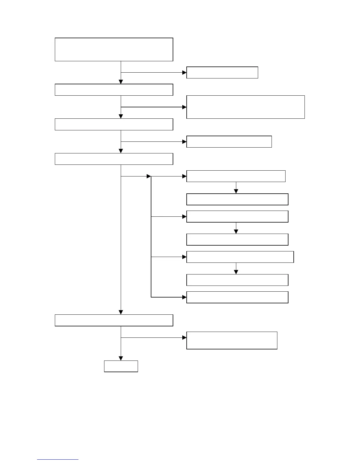
in is between 0.3V and 3.0V.
OK
NG
It is not inverter problem.
Check IC pin 3 around 5V.
OK
NG
Check Q1, Q2, Q8, D1, F1 and repair them.
Check one of these components was short
to GND.
Check CN2 and CN3 is connected right.
OK
NG
Check CCFL and repair them.
Check the IC pin 3 is PWM.
OK
NG
Check the IC pin 11 is triangle.
OK
NG
Check the Q4, Q10, R5, D5, L1
and repair them.
Check D2, C14, R11and repair them.
Check the IC pin 9 is 2.5V.
NG
Check R20 and R28 and repair them.
NG
Check the IC pin 8 feedback waveform.
Check CR1, CR2 and repair them.
NG
Repair the LM339.
OK
OK
OK
Check the buck circuit.
Next page

Table of Contents

Questions and Answers:

Question and Answer IconNeed help?

Do you have a question about the NEC MultiSync LCD1550ME and is the answer not in the manual?

NEC MultiSync LCD1550ME Specifications

General IconGeneral
BrandNEC
ModelMultiSync LCD1550ME
CategoryMonitor
LanguageEnglish

Related product manuals