TRANSIT ENTRY | INSTALLATION GUIDE
Connections
8/30
3 CONNECTIONS
3.1 CABLE CONNECTIONS
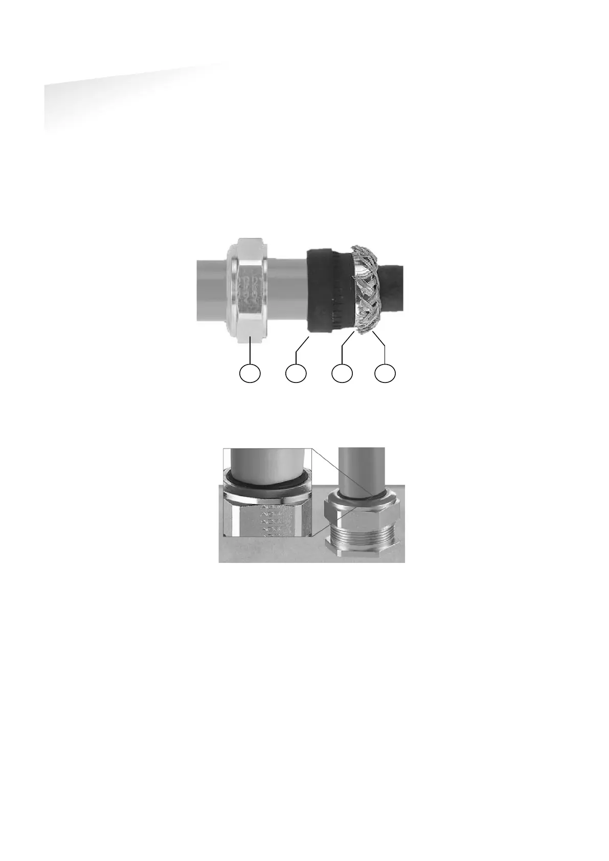
Cable connections to the TRANSIT Entry are made using the EMC cable glands.
Shielded cable shall be used for all connections including the DC-supply
connection.
Assembly instructions:
1 Push the cap nut (1),
seal insert (2) and
gland contact socket
(3) onto the cable.
2 Cut back the outer
sheath to desired
length.
3 Bend over the screen
braiding (4) over the
gland contact socket
and cut back the
screen braiding as
Figure 6: Cable shield
4 Screw the cap nut onto
reader part until the seal
insert is pushed out of the
gland. See Figure 7.
Figure 7: Gland tightening
Correct mounting and tightening the EMC cable glands is essential for water
protection.
See appendix
Error! Reference source not found.
A for detailed information on the
cable glands.