Do you have a question about the Nedap VP1007 and is the answer not in the manual?
The Nedap Velos VP1007 is an ISO Reader I/O device designed for animal identification in various agricultural applications such as feeding, weighing, milking, and heat detection. It serves as a crucial component in a larger system, communicating with a central computer or controller via CAN, RS485, or RS232 protocols. The VP1007 does not operate autonomously; it requires controlling commands from the connected computer to manage its inputs, outputs, and identification functions.
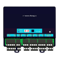
The primary function of the VP1007 is the identification of animals using ISO 134.2 kHz FDX/HDX tags. It is equipped with two antenna connections, though only one can be active at any given time, allowing for flexible antenna placement. Beyond identification, the device offers extensive I/O capabilities. It features five outputs designed to activate external equipment such as lights, motors, valves, and relays. Additionally, it provides five protected outputs that supply a continuous 25V, suitable for powering sensors. For data acquisition, the VP1007 includes five inputs that can read signals from various sensors or switches. Communication with the controlling computer is facilitated through RS232 or RS485 interfaces, enabling integration with systems like weigh computers. The device supports V-sense antennas, which are suitable for farm conditions and must be installed within an appropriate housing, such as a V-box.
The VP1007 is designed for ease of installation and adjustment. The installation process involves mounting the device, wiring all connections, powering it up, setting a unique address (especially when multiple VP1007 units are used), checking antenna adjustment, verifying connected equipment, and configuring the device in the PC software.
Upon power-up, the device performs an automatic antenna tuning process, with LEDs indicating the tuning status. A green LED signifies successful tuning, while red LEDs or blinking patterns indicate issues such as the antenna being out of range, not connected, or switched off by software. Each VP1007 requires a unique address on the communication bus, which can be set using the integrated display and push button. The display shows the current address, and a blinking pattern indicates when a setting is being stored. If the address is not accepted by the communication bus, it will remain displayed.
The device's inputs are continuously read, and any status changes are sent to the controller. Outputs are switched on or off based on commands from the controller. LEDs on the device provide visual feedback on its status, and any errors are communicated to the controller.
For advanced users, the VP1007 offers a service menu accessible via the display and push button. This menu allows for testing of individual inputs and outputs, which is useful for troubleshooting connected equipment. For example, users can activate specific outputs (e.g., a light connected to output 5) to verify functionality or read input states from sensors or switches.
Antenna adjustments can also be made through the service menu. The antenna power, which defaults to maximum (99), can be checked and modified to reduce the reading distance if necessary. The antenna squelch feature allows setting a threshold for the ID level of a tag, preventing weak tag numbers from being transferred to the software. This means the antenna power remains the same, but only strong signals are processed. The squelch level can be adjusted from a minimum of -0 (no threshold) to a maximum of -9.
An identification test option, "id," is available in the internal test menu. When a tag is in the antenna field, the green LED for antenna tuning blinks, and the last two digits of the tag number are displayed, confirming successful identification. Additionally, "SF" (FDX) and "SH" (HDX) signal level indication tests provide feedback on the signal strength received by the reader. This is particularly useful for HDX, where external influences can more easily affect the antenna field. By slowly moving an HDX tag into the antenna field, users can observe an increase in the display value, indicating proper signal reception. A negligible increase might suggest external noise interference, which could be caused by frequency-controlled electric motors or transmitters operating near 134.2 kHz.
The VP1007 is designed for minimal maintenance. No regular maintenance is required for the device itself.
Software updates, referred to as firmware, can be performed via the CAN-bus. In the Nedap Velos system, the web browser interface of the VPU (VP8001) is used to manage these updates. This ensures that the device can always run the latest software, incorporating new features or improvements.
Regarding cleaning, the VP1007 must be installed in a suitable housing, such as a V-box, which protects it from farm conditions. Therefore, direct cleaning of the VP1007 unit is generally not necessary.
In the event of errors or malfunctioning, the device provides diagnostic information through its LED indicators and the display menu. Indicator LEDs normally show green or off states, with red or orange indicating an issue. The "dE" option in the display menu allows users to view specific error codes, which can help in troubleshooting. These error codes cover a range of issues, including output current errors, short circuits, CAN bus problems, and input/output malfunctions. If an error is not cleared after being displayed, it indicates a persistent problem.
Identification performance can be affected by disturbances from variable-frequency drives (e.g., for ventilation, milk pumps, vacuum pumps) or fluorescent tube lighting. Troubleshooting such interference involves systematically switching off farm equipment to isolate the source, often revealing issues with installation or the absence of mandatory main filters.
| Category | I/O Systems |
|---|---|
| Manufacturer | Nedap |
| Model | VP1007 |
| Input Voltage | 24 VDC |
| Output Voltage | 24 VDC |
| Number of Inputs | 8 |
| Number of Outputs | 8 |
| Protection Class | IP20 |