VP1007-200PM-00 ISO Reader I/O Manual version 0.4 / Page 9
7 Trouble shooting
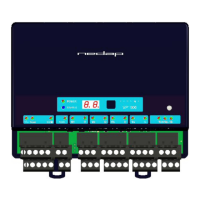
Errors / malfunctioning is indicated by the indicator LED’s or the display.
Error by indicator LED
Indicator LED’s are normally green or switched off. A red or orange indicator LED means normally
there is something not ok. See Appendix D for the explanation of the different colors.
Errors indicated at menu option “dE”
In menu option “dE” it is possible to see actual error codes. When entering the display menu option
“dE” the errors code will be shown and the error will be cleared. If the error is not cleared it means
there is still an error. There can be more than one error. Further errors are displayed one after another
with a short delay between each code.
“dE” code on the display Description
00 No errors
01 Max I out error, next module shut off
02 Short circuit detected at reset
03 Max I out high-side
04 Max I out low-side
05 CAN over voltage
06 CAN offset too high
07 -
08 -
09 Short circuit out5 <-> minus
10 Short circuit out4 <-> minus
11 Short circuit out3 <-> minus
12 Short circuit out2 <-> minus
13 OUT1 off : +24V on OUT1
14 Short circuit out1 <-> minus
15 IO5 off: +24V on OUT5
16 IO5 on: short circuit IO5
17 IO4 off: +24V on OUT4
18 IO4 on: short circuit IO4
19 IO3 off: +24V on OUT3
20 IO3 on: short circuit IO3
21 IO2 off: +24V on OUT2
22 IO2 on: short circuit IO2
23 IO1 off: +24V on OUT1
24 IO1 on: short circuit IO1
Identification performance and disturbance
Identification performance can be reduced by disturbance caused by variable-frequency drives used
for ventilation, milk pumps, vacuum pumps, etc. Also ballasts used for fluorescent tube lighting may
interfere. If there is interference one can locate the source by switching off all the equipment on a farm
and then switch them on again one by one. Most of the time when a variable-frequency drive is
causing a problem it is due to bad installation or without the mandatory main filters.