5 Operating and display elements Page 28
Stud welding unit operating manual Date: July 2021
ALPHA 850 07.2021 / EN Rev.: A
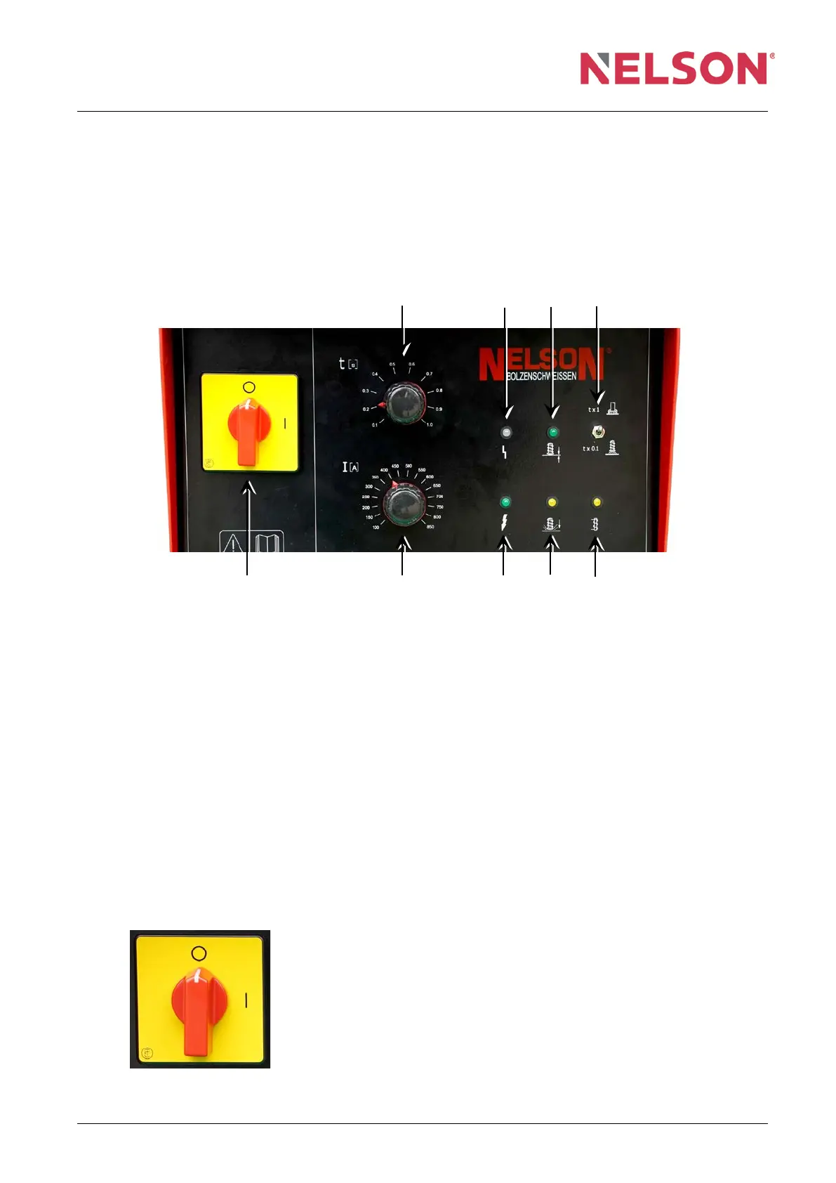
5 Control and display elements
All control and display elements of the ALPHA 850 welding device are on the upper
front plate and marked with graphic symbols.
3 7 8 9
1 2 4 5 6
1 Power switch 6 LED for gun coil circuit
2 Weld current potentiometer 7 Malfunction LED
3 Weld time potentiometer 8 Contact LED
4 System voltage LED 9 Operating mode selector switch
5 Start weld cycle LED
5.1 Operating elements
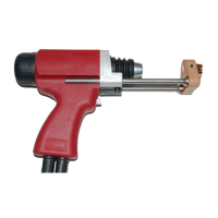
Power switch
Function: Turning the ALPHA 850 on and off.
Switch position: I = ON;
O = OFF
When the welding device is turned on, the system voltage
LED goes on. The network phases are monitored with the
fault LED.