Nelweld Operations and Service Manual
- 38 -
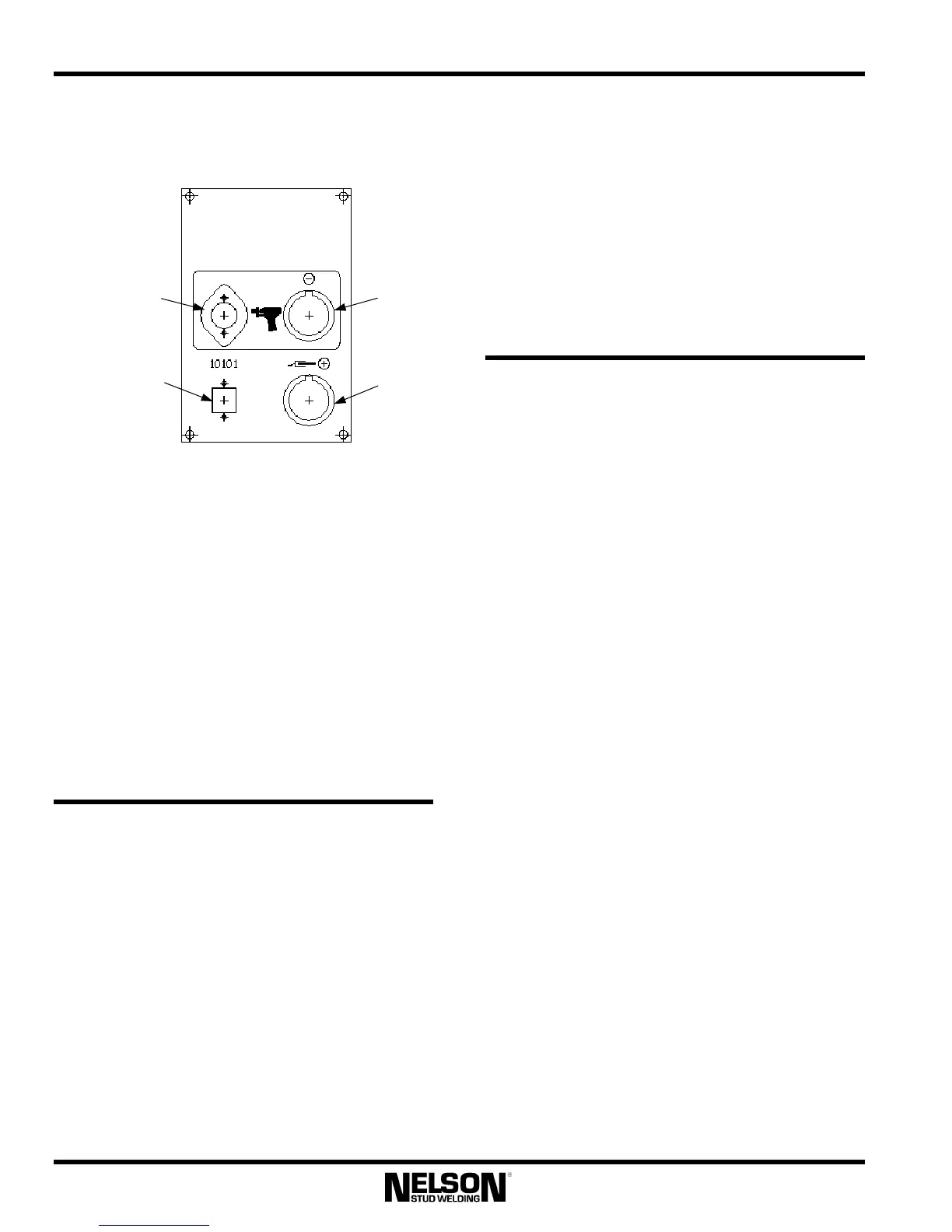
4.6.25 Output Panel Layout
Gun Control
Connector
Gun Weld
Cable
Connector
RS-232
Communications
Connector
Workpiece
Weld Cable
Connector
4.6.26 RS-232 Port /Cable
This port is accessed through the connector
shown on the output panel. It allows for
connection between the welder and a personal
computer or laptop, and is necessary for the use
of any additional Nelson software kits (Nelware
kits).
The isolated RS-232 interface cable that connects
the welder to the computer is sold separately. The
user can extend this cable up to 25 feet. With the
use of additional hardware, this distance is
virtually unlimited.
4.7 Custom Adjustments
4.7.1 Pilot Arc Time Adjustment
Pilot Arc Time is defined as the time the pilot arc
is turned on before main current flows and is
represented by t
3
on the “Timing Diagrams” in
the Section 7.1 of this guide. The factory default
setting for this parameter is 50 milliseconds
(0.050 seconds). For some applications, it may be
desirable to change this time setting. The Pilot
Arc Time can be adjusted using special function
F4.
4.7.2 Hot Plunge Time Adjustment
Hot plunge time is defined as the time main
current is on after the gun coil is shut off. It is
represented by t
5
on the “Timing Diagrams” in
the Section 7.1 of this guide. The factory default
setting for this parameter is 50 milliseconds
(0.050 seconds). For some applications with very
slow or very fast gun operation, it may be
desirable to change this time setting. The Plunge
Time can be adjusted using special function F3.
4.8 Accessories
This section specifies options that are available
for use with Nelweld units. Nelson Factory
Trained Personnel should install the kits where
specified. Where a connection to a computer is
required, an RS-232 port must be either factory or
field-installed. If Nelson software must be
installed on the computer as part of the kit, the
computer must meet the minimum specifications
set forth in the PC Requirements table. When
ordering kits, consult the part numbers listed in
the Nelweld Accessory and Kit Numbers table.
4.8.1 Caster Kits: User Install
The Nelweld power supplies are shipped from the
factory with legs installed on the base. If unit
mobility is a requirement, customer-installed
Caster Kits are available. The front casters swivel
to allow lateral motion while rear casters are
stationary. Each swivel caster is equipped with a
brake to prevent movement once the unit is
located in the desired position.
To install, unbolt the legs, place the casters over
the holes, and reattach the bolts. Opening the
cabinet is unnecessary.
4.8.2 Gas Valve Control Kit: Tech Install
The Nelweld units are designed to control a gas
valve using the Gas Valve Control Kit. One kit is
required per unit output. This kit may be either
installed by Nelson Factory Trained Personnel or
by the customer.