Nelweld Operations and Service Manual
- 53 -
t
1
t
2
t
3
t
4
t
5
Gas Valve
Gun Trigger
Main Arc
Pilot Arc
Feed Signal
Contact Lost
Feed Signal
After Weld
Gun Coil
Contact
Feed Signal
Contact Lost*
Feed Signal
After Weld*
Welding
Chuck
Saver
Welding
t
1
t
2
t
3
t
4
t
5
Chuck stripper and chuck saver operation
t
9
t
10
t
9
t
10
Chuck
Stripper
Chuck
Stripper
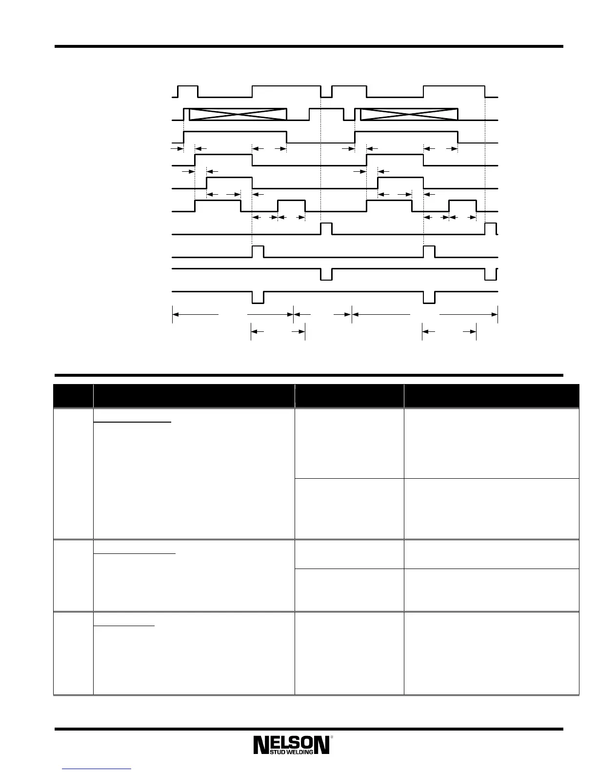
7.2 Timing Diagram Definitions
Symbol
Description Controlling Function
Values
Function F14
Enables/Disables Gas
Option
default
option
0 (off)
1 (on)
t
1
Gas Preflow Time
After the gun trigger is closed, the gas valve
is turned on for the preflow time before the
gun is lifted and before the pilot arc is turned
on. This allows time for the air to purge
from the gas line to insure that a gas shield
is present before starting an arc.
If another weld is started while ga
due to the postflow timer, the preflow is
aborted and the weld starts immediately.
Function F15
When Gas Option is Enabled,
Sets Preflow Time
default
minimum
maximum
500 ms
0 ms
5000 ms
Function F14
Enables/Disables Gas Option
default
option
0 (off)
1 (on)
t
2
Gas Postflow Time
After the weld is complete, the gas valve is
held on for the postflow time. This provides
a gas shield while the weld solidifies and
begins to cools.
Function F16
When Gas Option is Enabled,
Sets Postflow Time
default
minimum
maximum
500 ms
0 ms
5000 ms
t
3
Pilot Arc Time
When the gun trigger is closed, the gun coil
is energized and the pilot arc is turned on.
After the pilot arc time expires, the main arc
is turned on. This allows the gun time to lift
before main current flows.
Function F4
Sets Pilot Arc Time
default
minimum
maximum
50 ms
10 ms
100 ms