Nelweld Operations and Service Manual
- 26 -
3.7 Moving the Power Source
This equipment has been designed for
portability. Nelweld models are supplied from
the factory with legs in the four corners of the
base. This allows a forklift to lift these
machines from their front or the side for easy
relocation. There are also Caster Kits available,
which take the place of the stationary legs, for
those requiring continuous mobility. Once
positioned, the swivel casters should be locked
to prevent accidental movement.
The main cable is not a structural member, and
must not be used as a handle during transport.
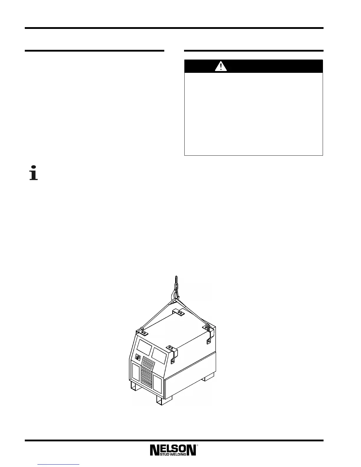
All Nelweld power sources have side
handles that can be used to help move a
power unit with a Caster Kit installed.
These are also designed to allow hoisting by
using a fabric slings, each at least 39” long and
having a load-carrying capacity of 1100 lbs (500
kg), strung diagonally through opposite corner
handles, as shown in Figure
3-1. The sling may
be strung through either two or four handles. If
the handles need to be removed, the screws
holding the handles in place must be retorqued
to 25 ft-lbs, otherwise handle failure may result
when lifting the unit.
3.8 Input Connections
3.8.1 Input Voltage Connection
The power switch on the front panel should be
turned to the off position before making any
power connections. Connections should be
made in accordance with all local and national
electrical codes, following the connection
diagram in Figure 3-2.
Use a three-phase supply line. Remove the left
side case side panel, with respect to the front of
the machine. A 2½ inch (63.5 mm) diameter
hole for the input supply is located on the lower
left of the rear cabinet panel.
Only a qualified electrician should connect
the input leads to the power source.
Connections should be made in accordance
with all local and national electrical codes,
following the connection diagram located on
the inside of the reconnect/input access
panel of the machine.
Failure to do so may result in bodily
injury or death.
Figure 3-1: Proper hoisting technique of a Nelweld power
supply using two handles.