Nelweld Operations and Service Manual
- 27 -
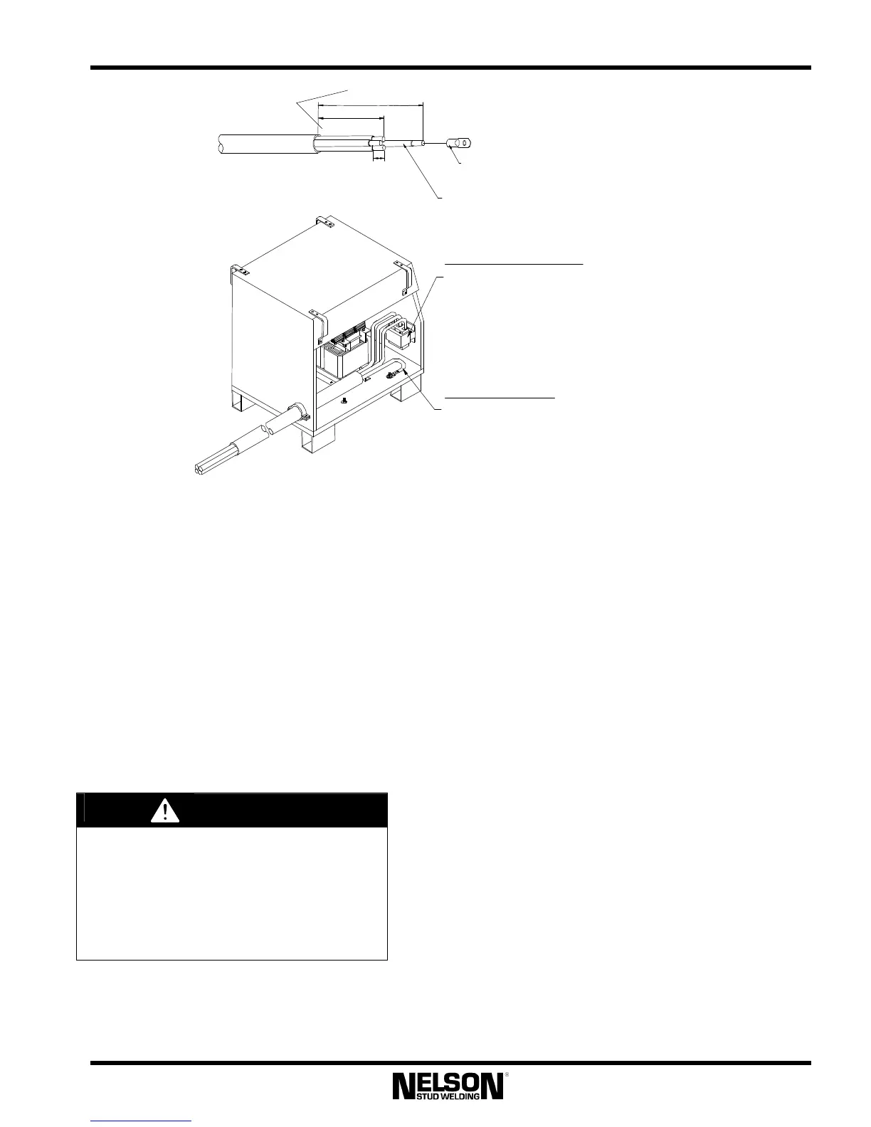
18" (457mm)
12" (305mm)
1" (25.4mm)
CRIMP ON WIRE LUG -
CABLE TO PRIMARY POWER
- ONE REQUIRED
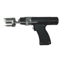
L1, L2 AND L3 CONNECTIONS
FIRMLY ATTACH THREE POWER LEADS, AS SHOWN.
COLOR AND POSITIONS IS NOT CRITICAL.
ENSURE THAT NO UNINSULATED WIRE IS
EXPOSED.
GROUND CONNECTION
FIRMLY ATTACH GREEN WIRE TO THE GROUNDING
STUD, AS SHOWN. (GREEN/YELLOW FOR CE UNITS)
VERIFY THAT LUG IS PROPERLY CRIMPED AND THAT
CONNECTION IS SECURE.
GREEN WIRE (GROUND)
(GREEN/YELLOW WIRE FOR CE UNITS)
FOR 3000 & 4000
MODELS, ADD 18” TO
THESE WIRE LENGTHS
Connect L1, L2 and L3 to the top of the front
mounted disconnect switch. Connect the
ground lead to the stud provided on the cabinet
floor.
Ensure that the transformer jumper links are
appropriately connected for the input line
voltage being supplied, as shown in Figures 3-3,
3-4, and 3-5. Removing the upper case panel
and handles are not required in order to change
jumper settings, and is not recommended.
Figure 3-2: Connecting the input power cables
When changing jumper links, DO NOT
OVERTIGHTEN NUTS, otherwise,
damage may occur to the Nelweld unit.
Additionally, do not lubricate the posts,
nuts, or jumpers.