4. DESIGN
Microinverter technology greatly simplies the design process compared to
convenonal string inverter systems. The BD-600 allows for the PV modules to be
placed with dierent azimuths and orientaons to maximize site generaon. In
addion to the layout conguraon, a successful design needs to take into account
two other consideraons: branch circuit sizing and voltage rise calculaon.
Layout: A layout map showing the locaon of ea
ch PV module and its
corresponding microinverter should be rst constructed. Care should be taken to
review the DC lead length of the PV modules to see if addional jumpers are
required to reach the dual DC inputs of the BD-600. Each microinverter comes with
a number of peelable serial number sckers. Remove a pair of sckers and h
them to the corresponding modules on the site map.
Branch Circuit Sizing: Since the BD-600 uses #12 AWG cabling, NEC
code species a
maximum breaker size of 20A. This limits the branch size to a maximum of seven
(7) devices for a 240V system and six (6) devices for a 208V system.
Voltage Rise Calcula�on: The addion of daisy chained, current producing
microinverters on the AC bus results in a sequenal rise in voltage along the bus,
with the highest at the furthest device. Care must be taken that the resulng
voltage doesn’t exceed the maximum permissible by code. Fo
r a 240 V system, this
is 264V and 229V for a 208V system. Please contact NEP technical support should
you need more informaon on this subject.
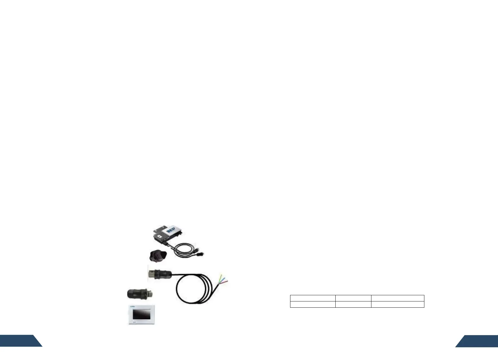
5. PARTS NEEDED
5.1 NEP Parts
In addion to the micro inverters, you’ll need the following parts from NEP:
● AC trunk cable (one per micro)
● Protecve end cap (one per branch circuit)
● Tail cable (one per branch circuit- 16’ long)
● Male connector (oponal)
Used to make extension cables
● BDG-256 (or BDG-256P3)
5.2 Addi�onal Parts and Tools Required
In addion to the PV modules, racking, and associated hardware, you’ll need the
following parts:
MLPE rail or frame ach clamps (2 per microinverter)
• AC juncon boxes (mulple opons possible)
• Cordgrip with locknut or strain relief ng (one per branch circuit)
• A subpanel may be required for systems with mulple branch circuits
• Cable clips
• Sockets, wrenches, torque wrench, mulmeter, small at head screwdriver,
and mirror with extension rod
• Lightning and surge suppressor (recommended)
5.3 Lightning and Surge Suppression
Since the NEP Limited Warranty does not cover “acts of God”, such as lightning
strikes or grid irregularies, NEP strongly recommends inclusion of a surge
protecon device in all systems. Lightning does not actually need to strike the
equipment or building where PV system is installed to cause damage. Oen, a
strike nearby will induce voltage sp
ikes in the electrical grid that can damage
equipment. Addionally, many areas can experience irregularies in electrical
grid that can generate similar voltage spikes. While the BDM-600 includes
integrated surge protecon circuitry, if the surge has sucient energy the
protecon circuitry can be exceeded and the equipment can be damaged.
Installaon of a suitable surge protector signitly increases the protecon
against such
events.
5.4 Shipping Informa�on
The BDM-600 Ships six (6) to a box with each box measuring approximately 18” x
13.5” x 16”and weighing 57 lbs. A typical pallet contains 27 boxes.
6. INSTALLATION
6.1 Pre-installa�on
Prior to installaon, use the mulmeter to check the electrical panel to conrm
the correct service voltage per the below table. If this voltage is too high it can
prevent proper operaon of the microinverters. If this is the case, the ulity
should be noed. However, an NEP technical representave may be able to
adjust microinverter operaonal parameters to accommodate the situaon.
Also, please check all microinverters and cabling for any potenal damage prior
to site deployment. Remember to rst create and bring a copy of the layout map.
This map should show the physical locaon of each BDM-600 and their
associated PV modules in your installaon.