26
NETAJET
™
4G INSTALLATION MANUAL
ON-SITE PREPARATIONS
Infrastructure requirements
In order to enable the operation of the NetaJet™ 4G it is essential to meet the specific requirements for each
mode such as main line pressure and infrastructure conditions. See the relevant mode description (pages 14-24).
NOTE
To ensure flow rate stability, the consumption of the different irrigation shifts should be as equal as
possible. Each changeover between shifts with different consumption will result in consumption
fluctuation, affecting the EC and pH stability. The consumption of the smallest shift should not be
less than 75% of the consumption of the largest shift.
Pump house (Filter house / Fertilizer house) requirements
Sufficient space should be available between the fertilizer/acid tanks and the NetaJet™ 4G to allow
inspection and maintenance operations.
CAUTION
The NetaJet™ 4G should be:
• placed in a roofed building
• protected from direct sunlight
• kept at an ambient temperature between 10°C and 40°C (50°F and 104°F)
• kept at a maximum relative air humidity of 85%
• properly ventilated
• protected from dust
• protected from splashes or direct spraying with water or chemicals
NOTE
In order to prevent penetration of fertilizer or acid into the soil, it is recommended that the floor
of the pump house have a minimum slope of 1% towards a gutter at its lower edge and an
underground tank at the lower end of the gutter, enabling drainage of any spill or excess.
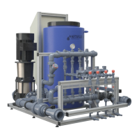
The water distribution system
For the setup of the water distribution system, the following components should be installed according to
the mode of the NetaJet™ 4G. See the relevant mode description (pages 14-24)
Components of the water distribution system
Component Specifications
23
Main line pump
Suitable for flow rate satisfying the maximum field requirement (ensure stable pressure).
24
Main line filter
≤ 130 µm (≥ 120 mesh).
25
Main line
water meter
With electrical pulses. The pulse should be as short as possible according to the
filling line diameter and the controller's limitations.
(See Recommended flow meter pulse rate table, page 29)
26
Main line PSV
Installed on the main line upstream from the irrigation valves.
27
Manual valve
(isolation)
Manual ball valves at the NetaJet™ 4G inlet and outlet.
For isolation of the NetaJet™ 4G during maintenance
28
Irrigation valve
29
Fertilizer/acid filter
≤ 130 µm (≥ 120 mesh)
30
Manual valve
(fertilizer)
A manual ball valve on each fertilizer/acid line at the stock tank outlet
31
Fertilizer/acid
stock tank
Up to 8 fertilizer/acid solution stock tanks.
 Loading...