NETAJET
™
4G INSTALLATION MANUAL
39
SYSTEM CALIBRATION
Each NetaJet™ 4G is supplied fully calibrated according to the main irrigation line flow rate and pressure
reported by the client, and does not require any additional calibration during installation.
The proper pressure regime of the NetaJet™ 4G
Mode
Required pressure - bar (PSI)
A
Inlet PRV
B
Lower manifold
C
Outlet PSV
D
Main line
BP PL,
IL PL,
High-flow,
Octa
3.5-4.0 (50.7-58.0) 0-+0.5 (0-7.2) 4.0 (58.0)
Standard:
2.5-5.8 (36.5-84.0)
High pressure:
5.8-7.5 (84.0 -108.5)
BP ST,
IL ST
3.5-4.0 (50.7-58.0) 0-+0.5 (0-7.2) 0-+0.5 (0-7.2)
In the rare event that the main line pressure
D
is out of the NetaJet™ 4G working range (higher or lower):
1)
Restore the
main line pressure to the original value according to the reference data in the
NetaJet™ 4G Hydraulic Conditions Checklist (User Manual, page 45).
2) If it is impossible to restore
the
main line pressure according to the reference data - alter the system
calibration according to the actual main line pressure.
The calibration process involves checking the pressure at several points on the NetaJet™ 4G and
readjusting the system pressure regime.
Contact your local Netafim™ representative for guidance.
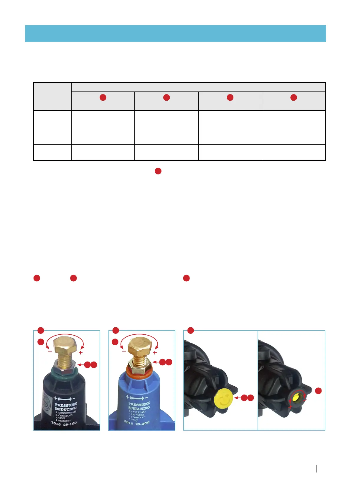
Each mode has between 2 to 3 points to attend to. At each point there is a pressure gauge and a valve
(PSV or PRV) to adjust.
2
1. Release the pilot lock-nut.
2.
Gently rotate the pilot calibration bolt with a
spanner.
3.
After completing recalibration of the system,
tighten the pilot lock-nut.
A
Inlet PRV,
C
Outlet PSV
B
Lower manifold (compensation channel PRV)
1. Remove the yellow/white cap.
2.
Gently rotate the pilot calibration screw with a
screwdriver.
3.
After completing recalibration of the system,
replace the yellow/white cap.
1
2
1
2
3
3
A C B
1 3
The illustrations on the next page will assist you in locating each calibration-point pressure gauge and valve
for each NetaJet™ 4G mode.
 Loading...