30
NETAJET
™
4G INSTALLATION MANUAL
INSTALLATION
Unpacking and placement
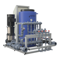
Check the ShockWatch label attached to the
packaging and ensure the indicator is white.
If the indicator is red - follow the instructions
on the ShockWatch label.
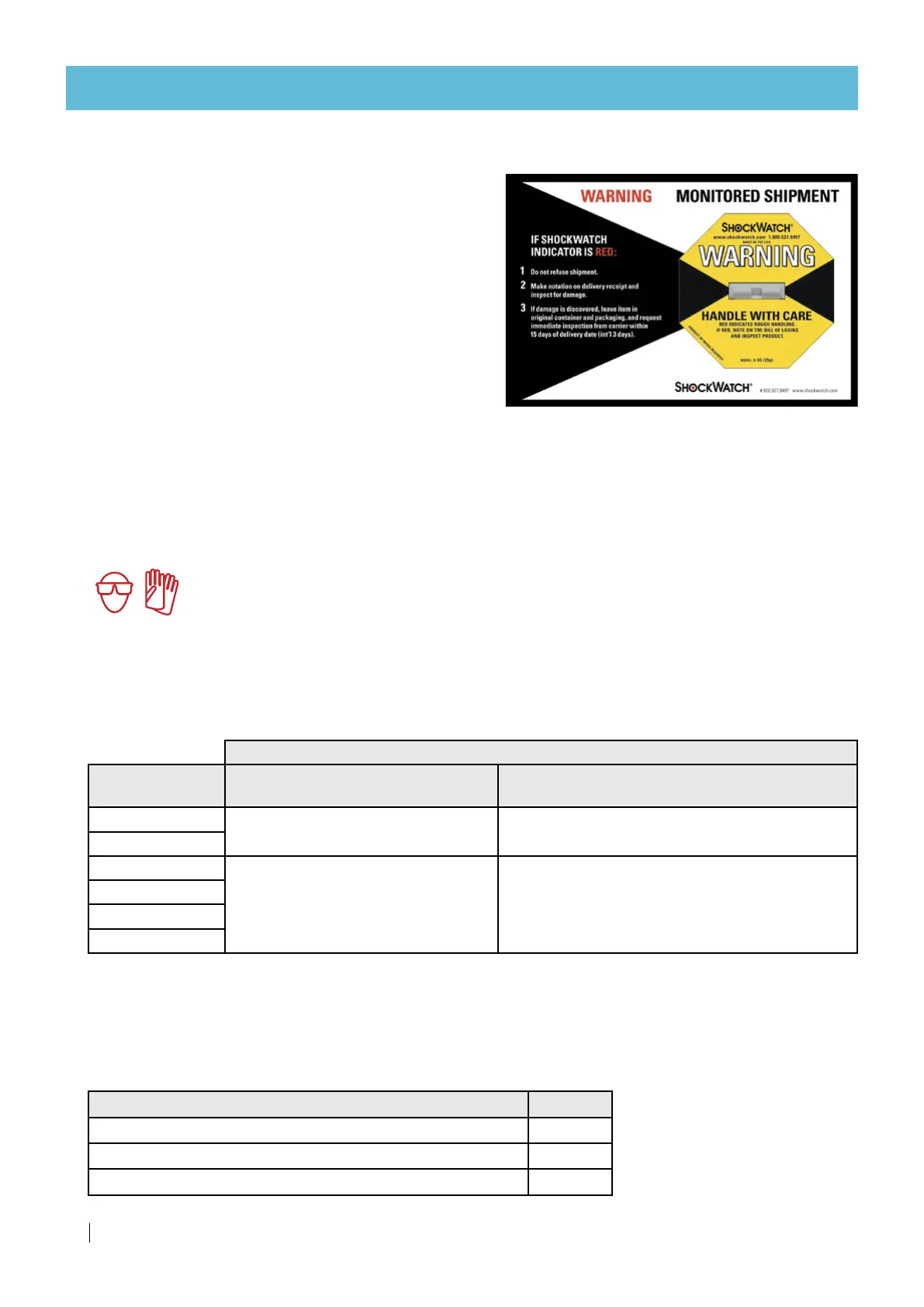
Using forklift, place the NetaJet™ 4G package
close to the irrigation system.
Carefully open the packaging.
Remove the 4 screws and bolts connecting the
NetaJet™ 4G to the wooden pallet.
Remove the plastic cover (if there is one) from the controller.
Place the NetaJet™ 4G in its position.
Adjust the legs so that the NetaJet™ 4G is steady.
Hydraulic installation
WARNING
Always use protective equipment, gloves and goggles when handling fertilizers, acid and
other chemicals!
Main line inlet/outlet connection
Connect the appropriate pipes to the inlet and the outlet of the NetaJet™ 4G according to the mode of the
system (see Location of inlet, outlet and fertilizer/acid line connectors, page 28).
Diameter
Mode
PVC, adaptor union - glue connector
(installed)
PVC, BSP or NPT nipple - male thread connector
(supplied)
BP PL
50 mm 1.5"
BP ST
High-flow
63 mm 2"
Octa - 8-channel
IL PL
IL ST
Stock tank connection
Connect the fertilizer lines to the NetaJet™ 4G according to the mode of the system
(see Location of inlet, outlet and fertilizer/acid line connectors, page 28).
Three types of connection are available
Fittings (interchangeable)
Diameter
PVC, hose nozzle insert connector (installed) 16 mm
PVC, nipple - male thread connector (supplied) 1/2"
PVC, half union - female thread connector (supplied) 3/4"
 Loading...