NETAJET
™
4G INSTALLATION MANUAL
29
ON-SITE PREPARATIONS
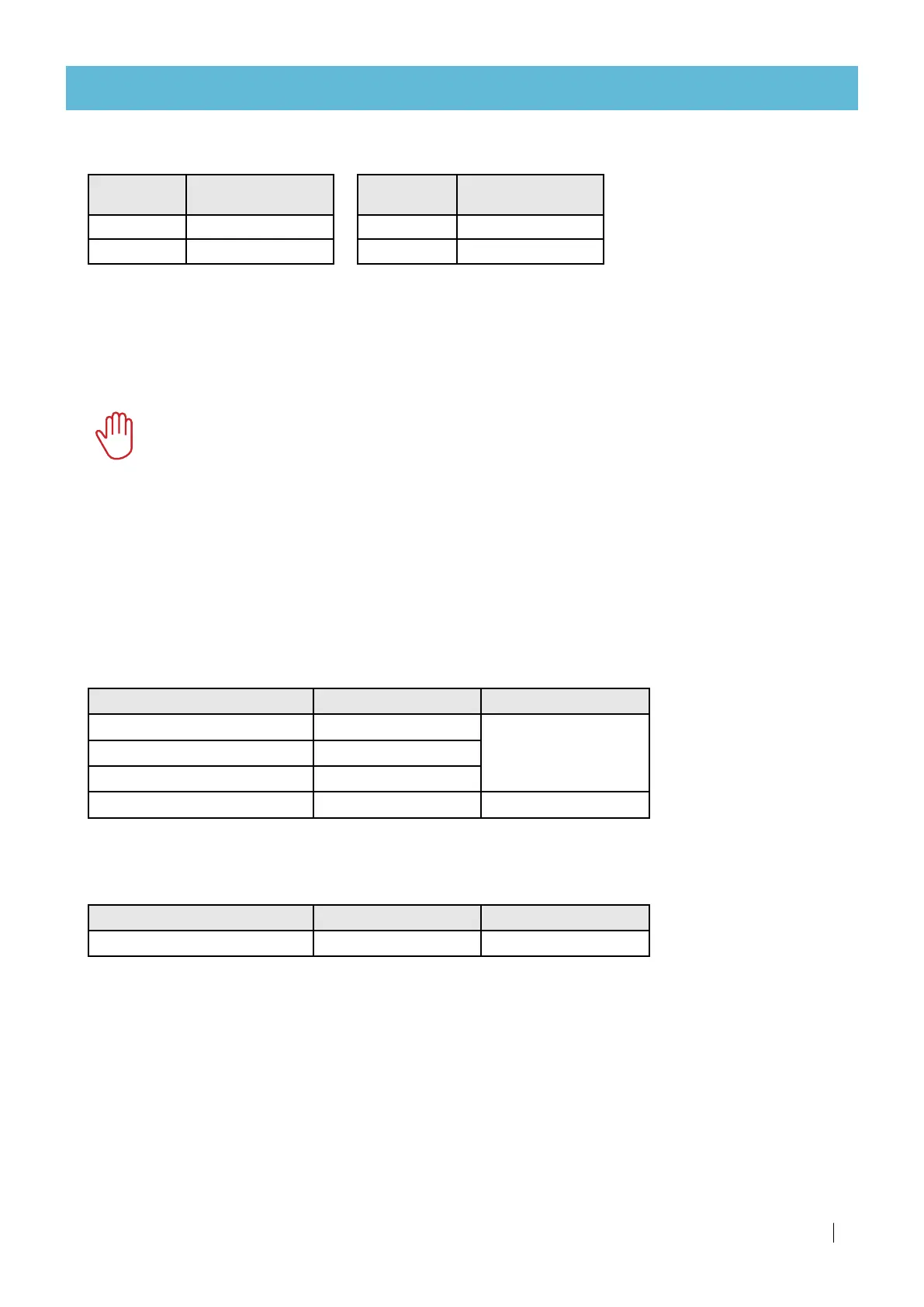
Recommended flow meter pulse rate*
Flow rate
m
3
/hr
Flow meter output
l/pulse
Up to 6 1
6-60 10
Flow rate
GPM
Flow meter output
US gal/pulse
Up to 88 1
88-1000 10
*Compatible with Netafim™ NMC controllers. In cases where the NetaJet™ 4G is to be controlled by a
third-party controller, consult Netafim™.
Electrical preparation
Mains connection
CAUTION
Only qualified electricians are permitted to perform electrical installations!
The following components must be provided for the installation:
• A readily accessible circuit breaker, rated according to the NetaJet™ 4G total rated power, certified as a
branch circuit over current protector compliant with the national code and requirements.
• Grounding connection: ≤ 10 Ω.
Mains wire size
For all modes that include a dosing booster
For the selection of the wire size - consider the NetaJet™ 4G total rated power:
5 wires: GND, N, L1, L2, L3
Power source required (kW)
3 X 220-277 VAC 3 X 380-480 VAC
Up to 3
≥ 2.5 mm
2
(≤ 13 awg)
≥ 2.5 mm
2
(≤ 13 awg)
3-4 ≥ 4 mm
2
(≤ 11 awg)
4-6 ≥ 6 mm
2
(≤ 9 awg)
6-8 ≥ 10 mm
2
(≤ 7 awg) ≥ 4 mm
2
(≤ 11 awg)
For the BP ST mode
The BP ST mode does not include a dosing booster. The mains feeds the controller only.
3 wires: GND, N, L
Power source required (W)
1 X 100-115 VAC 1 X 200-250 VAC
250 ≥ 1.5 mm
2
(≤ 15 awg)
≥ 1.5 mm
2
(≤ 15 awg)
 Loading...