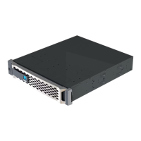
Blue PSU locking tab
5. Install the replacement PSU in the controller module:
a. Using both hands, support and align the edges of the replacement PSU with the opening in the
controller module.
b. Gently push the PSU into the controller module until the locking tab clicks into place.
The power supplies will only properly engage with the internal connector and lock in place one
way.
To avoid damaging the internal connector, do not use excessive force when sliding
the PSU into the system.
6. Reconnect the D-SUB DC power cable:
a. Plug the power cable connector into the PSU.
b. Secure the power cable to the PSU with the thumbscrews.
Once power is restored to the PSU, the status LED should be green.
7. Return the failed part to NetApp, as described in the RMA instructions shipped with the kit. See the
Part Return & Replacements page for further information.
Replace the real-time clock battery - AFF A70, AFF A90
You replace the real-time clock (RTC) battery in the controller module so that your
system’s services and applications that depend on accurate time synchronization
continue to function.
• You can use this procedure with all versions of ONTAP supported by your system.
• All other components in the system must be functioning properly; if not, you must contact technical support.
Step 1: Shut down the impaired controller
Shut down or take over the impaired controller using one of the following options.
91