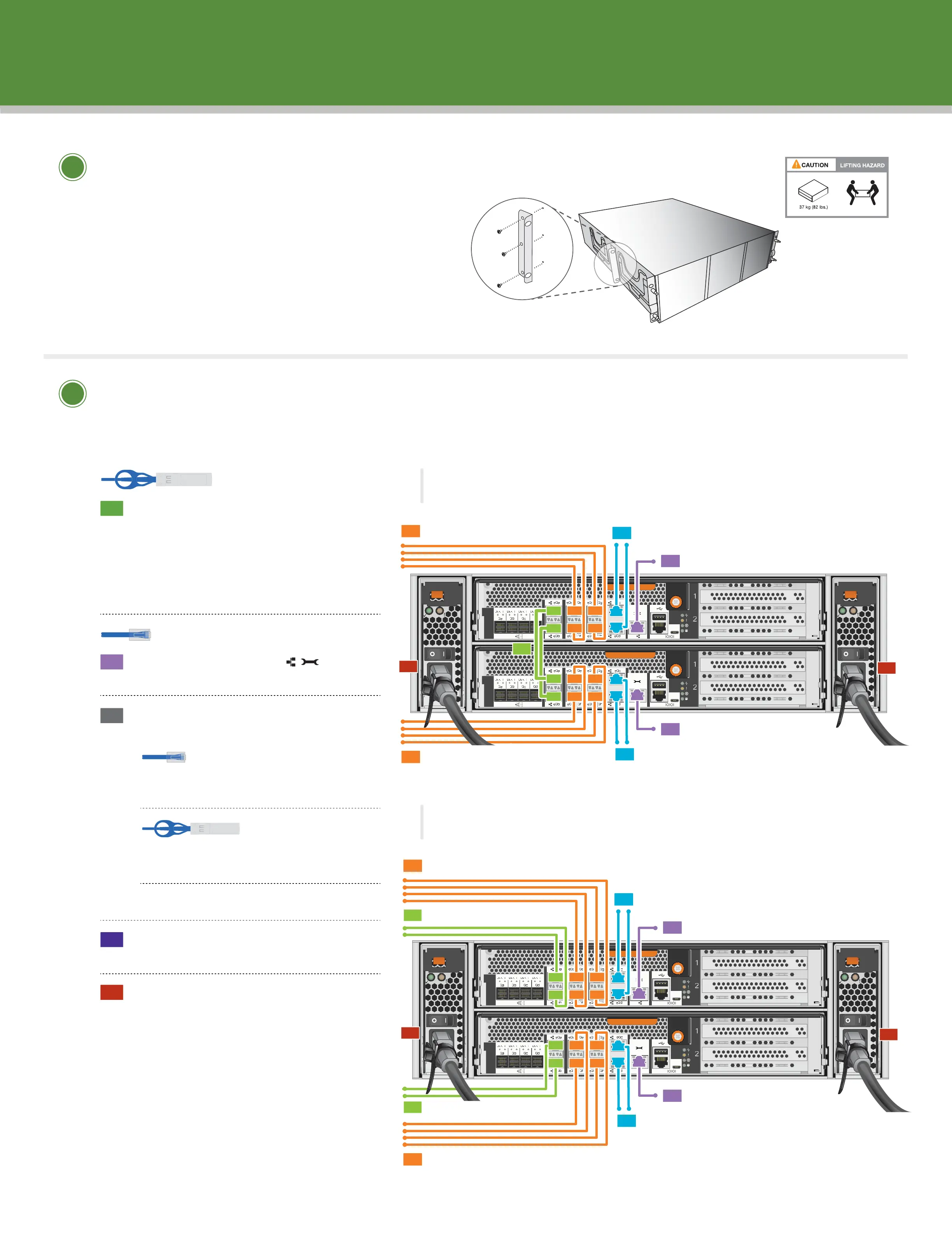
Install hardware | Stage 2
Optional 2-post
mid-mount brackets
• Unpack all boxes and inventory contents.
• Install rail kits, as needed, using the enclosed
installation instructions.
• Install system components on rails or in a
system cabinet per installation instructions.
• Attach cable management arms.
• Place the bezel on the front of the system.
Unpack and install system
3
4
5
1
2
1
2
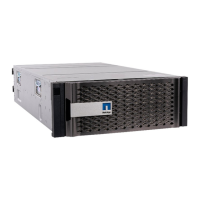
Cluster interconnect cable
(
PN 112-00297 or 112-00299)
Ethernet cables
Ethernet cables
To 10 GbE data network switches
3B
2
To management network switches
3A
To 10GBASE-T data network switches
3A
To 10GBASE-T data network switches
2
To management network switches
5
5
To cluster network switches
1
To cluster network switches
1
To 10 GbE data network switches
3B
Switched ONTAP
B
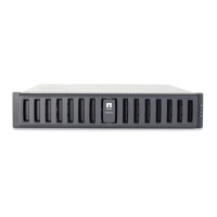
To 10 GbE data network switches
3B
2
To management network switches
3A
To 10GBASE-T data network switches
3A
To 10GBASE-T data network switches
2
To management network switches
1
5
5
To 10 GbE data network switches
3B
Switchless ONTAP
A
Cable controller for switchless ONTAP (option A)
or for switched ONTAP (option B)
See your network administrator for help connecting to your switch.
OPTION A: Cable the cluster
interconnect e0a to e0a and e0b
to e0b ports on both controllers.
OPTION B: Cable e0a and e0b
on both controllers to cluster
network switches.
Connect wrench ports
to the management switch.
Your network topology defines the
data network switch connections:
OPTION A: Connect 10GBASE-T
ports e0c and e0d to the switches
OPTION B: Connect e0e|0e through
e0h|0h to the switches
OPTION C: Do Option A and Option B
Strap the cables to the cable
management arms. (not shown)
Cable both power supplies
for each chassis.
ALL power cords MUST be used for all units.
10 GbE network cables
(
PN 112-00299 or 112-00300 or 112-00301)