We recommend using the following cables and, if applicable, SFP modules:
• Category 5e (Cat 5e) or better cable for a copper port at 1 Gbps or 2.5 Gbps.
• NETGEAR AGM734 module for a copper port at 1 Gbps.
• NETGEARAGM731ForAGM732Fmoduleforaberportat1Gbps.
• NETGEAR AXM761, AXM762, AXM763, AXM764, or AXM765 module for a
berportat10Gbps.
• NETGEARAXC761(1m),AXC763(3m),AXC765(5m),AXC767(7m),
AXC7610(10m),AXC7615(15m),orAXC7620(20m)cableforaberport.
Note: If purchased, SFP modules and cables are shipped separately.
This switch is designed for indoor use only. If you want to connect it to a device
located outdoors, the outdoor device must be properly grounded and surge
protected, and you must install an Ethernet surge protector inline between the
switch and the outdoor device. Failure to do so can damage the switch.
Before connecting this switch to outdoor cables or devices, see
https://kb.netgear.com/000057103 for safety and warranty information.
Log in and congure the switch
Youcanloginandconguretheswitchthroughtheout-of-band(OOB)port
(which is also referred to as the service port), through any Ethernet network port,
or through a console port. By default, the switch functions as a DHCP client.
Tologinandconguretheswitch,useone of the following methods:
• Audio-video local browser user interface.Usetheaudio-videolocal
browseruserinterface,abbreviatedasAVUI,throughtheOOBportorany
Ethernet network port (see Access the AV UI or main UI to congure the
switch).
• Main local browser user interface. Use the main local browser user
interface,abbreviatedasmainUI,throughtheOOBportoranyEthernet
network port (see Access the AV UI or main UI to congure the switch).
• CLI.Usethecommand-lineinterface(CLI)throughtheType-CUSBconsole
portorRJ-45RS232consoleport.YoucanconguretheIPaddressmanually
orusetheezcongutility(seeAccess the CLI to congure the switch).
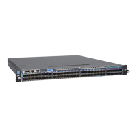
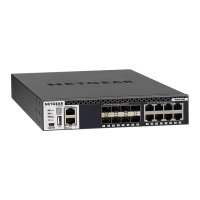
AV Line of Fully Managed Switches
M4250 Series
Set up the switch
Prepare the installation site so that mounting, access, power source, and
environmental requirements are met.
Note: For more information about these requirements, the hardware setup
process,theLEDs,andhowtoconnectdevices,seethehardwareinstallation
guide, which you can download by visiting
https://www.netgear.com/support/download/.
1. Install the switch using one of the following methods:
• On a at surface. Attach one of the rubber footpads that came with the
switch on each of the four concave spaces on the bottom of the switch.
• In a rack.Usetherack-mountkitthatissuppliedwithyourswitch.
2. Apply AC power.
ThePowerLEDlightssolidyellowwhiletheswitchconductsapower-onself-
test(POST).AfterthePOSTcompletes,thePowerLEDindicatestheresults:
• Solid green. The switch is functional.
• Solid yellow.ThePOSTfailed.
IfthePowerLEDdoesnotlightatall,checktoseethatthepowercableis
plugged in correctly and that the power source is functioning.
3. Connect devices to the switch.
Access the AV UI or main UI to congure the switch
You can use a computer on the same subnet as the switch to access either the
AVUIormainUIovertheswitch’sdefaultIPaddress.
1. CongureyourcomputerwithastaticIPaddress:
• ForaccessovertheOOBport,useanIPaddressinthe192.168.0.0/16
subnet.Forexample,use192.168.0.100.
• For access over an Ethernet network port, use an IP address in the
169.254.0.0/16subnet.Forexample,use169.254.100.201.
2. Connect an Ethernet cable from an Ethernet port on your computer to the
OOBportoranEthernetnetworkportontheswitch:
3. LaunchawebbrowserandenterthedefaultIPaddressoftheswitchinthe
addresseldofthebrowser:
• OOB port: Enter http://192.168.0.239.
• Any Ethernet network port: Enter http://169.254.100.100.
The login page displays.
4. Tologinforthersttime,dooneofthefollowing:
• AV UI. To access the AV UI, enter admin for the user name, leave the
passwordeldblank,andclicktheAV UI Login button.
• Main UI. To access the main UI, click the Main UI Login button. The
main UI login page displays. Enter admin for the user name, leave the
passwordeldblank,andclicktheLogin button.
Onrstlogin,youarerequiredtospecifyapassword.
5. Specify a password and log in again using your new password.
6. Conguretheswitchsettings.
OneachUIpage,ifyoumakechanges,besuretosavethechanges.
IMPORTANT: Makesurethattheswitchisrunningthelatestrmwareversion.
Todownloadrmware,visithttps://www.netgear.com/support/download/.
Note: For more information about using the main UI or AV UI, including
information about how to assign a static IP address to the switch, see one of the
user manuals, which you can download by visiting
https://www.netgear.com/support/download/.