Page 5 of 19
Figures
Figure 1-1. Package Contents........................................................................................................................................................................................8
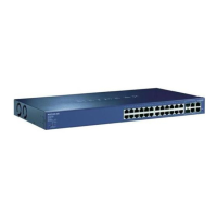
Figure 2-1. Front Panel of the NETGEAR ProSafe FS726TP Smart Switch with PoE ............................................................................................9
Figure 2-2. Back Panel of the NETGEAR ProSafe FS726TP Smart Switch with PoE.............................................................................................9
Figure 3-1. Example of Desktop Switching...............................................................................................................................................................12
Figure 4-1. Attaching Mounting Brackets.................................................................................................................................................................13
Figure 4-2. Connecting Devices to the Switch.........................................................................................................................................................13
Figure 4-3. Installing a Gigabit Ethernet Module into FS726TP...........................................................................................................................14
Tables
Table 2-1. Front Panel LEDs:...........................................................................................................................................................................................10
Table 4-1. Site Requirements ..........................................................................................................................................................................................12
Table B-1. Troubleshooting Chart ..................................................................................................................................................................................17
 Loading...
