[ENG] UniPing server solution v4/SMS & UniPing server solution v3, User guide -[USS] Sockets and Indication Elements
[USS] Sockets and Indication Elements
–
[USS] Sockets and Indication Elements
POWER LED
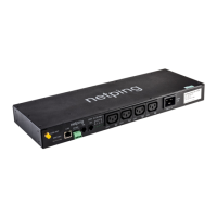
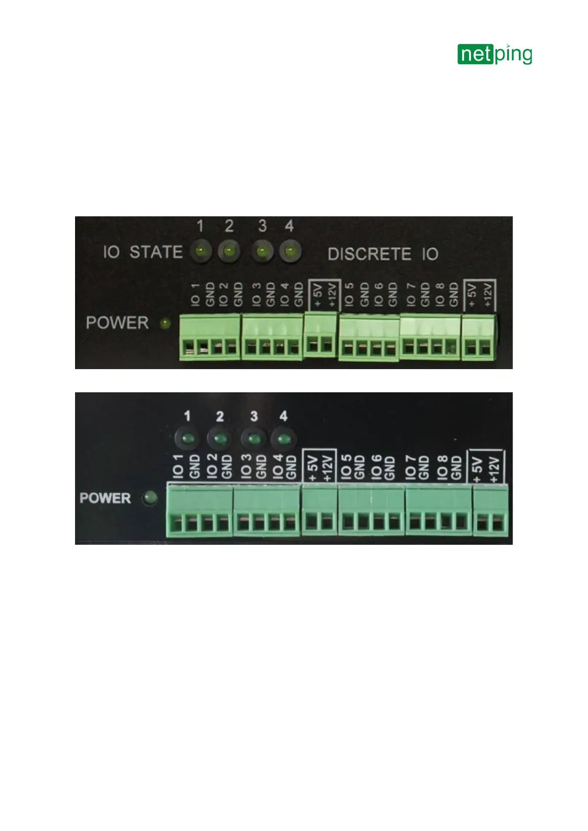
A POWER LED (see picture 1 and picture 2), when turned on, means that the device works.
IO Lines Connection Terminals
Picture 1–A terminal block for connecting IO lines (UniPing server solution v4/SMSmonitoring unit)
Picture 2– A terminal block for connecting IO lines(UniPing server solution v3monitoring unit)
DISCRETE IO terminal block is used to connect universal IO lines.
There are eight IO lines in a block. For each line, there are two contacts: IO and GND. To make connecting sensors
convenient, there are terminals +5 V and +12 Vin a DISCRETE IO block. A maximum summed current on+5V and
+12V terminals is 200mA, it is limited by a self-resetting fuse. To recover a terminal operation after a reboot, there is
a need to deenergize a devicecompletely for 30 minutes.
Electrical specifications of IO lines in the "output" mode:
Voltage of the logic "1": 4V, maximal current is: 0.3 mA
Voltage of the logic "0": 0,1V, maximal current is: 0.8 A
Electrical specifications of IO lines in the "input" mode:
Voltage of the logic "1": >2.1V