NV-202 VDSL2 Bridge with DIP Switch USER’S MANUAL Ver. A4
17
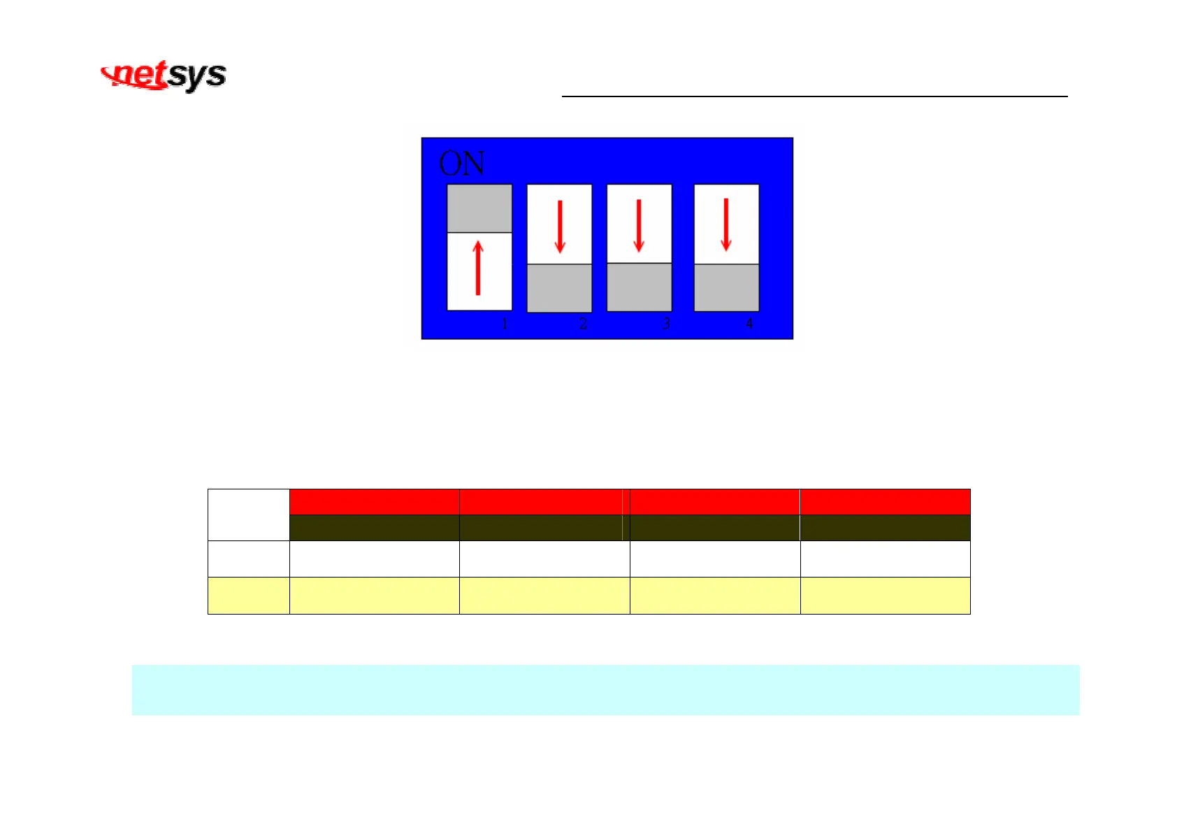
Figure 3.3 DIP switch setting
The following is table of DIP Switch configuration. (Table 3-4)
Table 3-4 DIP Switch Configuration
Pin 1 Pin 2 Pin 3 Pin 4
On/OFF
CO/CPE Mode Band SNRM Interleave / INP
On CO Mode High Band 9db 8ms / INP=2
Off CPE Mode Low band 6db 1ms / INP=0
Note:
1. The DIP switch default values are OFF.
2. Please power off NV-202, before making any transmission mode configuration.